


Conformément aux directives de la CNIL, pour poursuivre votre navigation dans de bonnes conditions vous devez accepter l'utilisation de Cookies sur notre site.


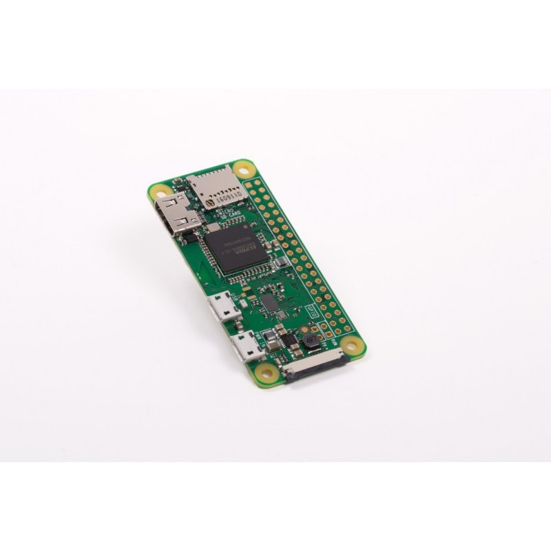 RASPBERRY PI ZERO W
-
15,00 €
RASPBERRY PI ZERO W
-
15,00 €
 MODULE RASPBERRY-PI3 B+ 1.4Ghz WIFI+BLUETOOTH
-
54,00 €
MODULE RASPBERRY-PI3 B+ 1.4Ghz WIFI+BLUETOOTH
-
54,00 €
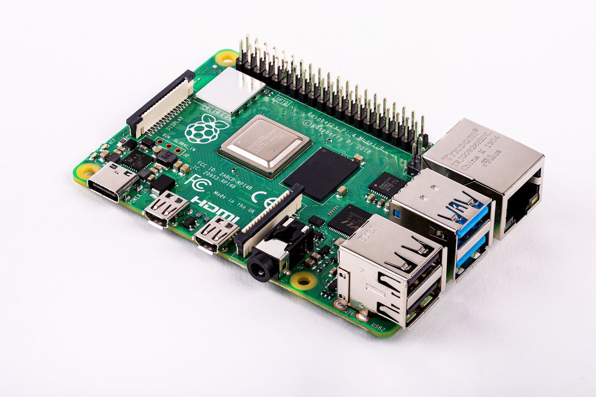
 MODULE RASPBERRY PI 4 4GO -MOD B QUAD CORE-A72 1.5GHz
-
82,00 €
MODULE RASPBERRY PI 4 4GO -MOD B QUAD CORE-A72 1.5GHz
-
82,00 €
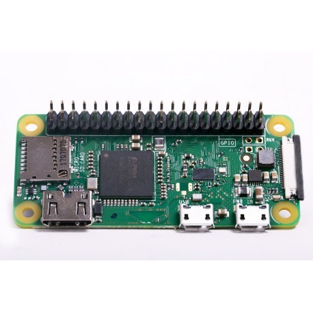 RASPBERRY PI ZERO WH
-
22,00 €
RASPBERRY PI ZERO WH
-
22,00 €
 MODULE RASPBERRY PI 4 1GO -MOD B QUAD CORE-A72 1.5GHz
-
44,00 €
MODULE RASPBERRY PI 4 1GO -MOD B QUAD CORE-A72 1.5GHz
-
44,00 €
 MODULE RASPBERRY PI 4 2GO -MOD B QUAD CORE-A72 1.5GHz
-
65,00 €
MODULE RASPBERRY PI 4 2GO -MOD B QUAD CORE-A72 1.5GHz
-
65,00 €
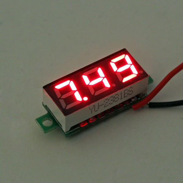 Voltmètre numérique testeur rouge auto-alimenté
-
7,80 €
Voltmètre numérique testeur rouge auto-alimenté
-
7,80 €
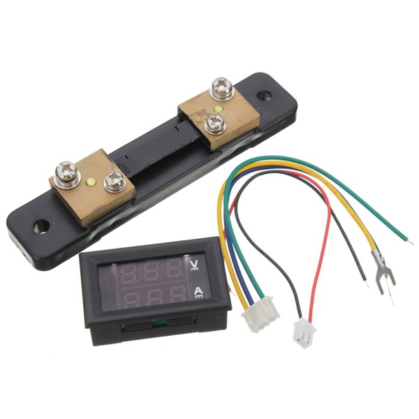 Voltmètre et ampèremètre 100v 50amp
-
18,00 €
Voltmètre et ampèremètre 100v 50amp
-
18,00 €
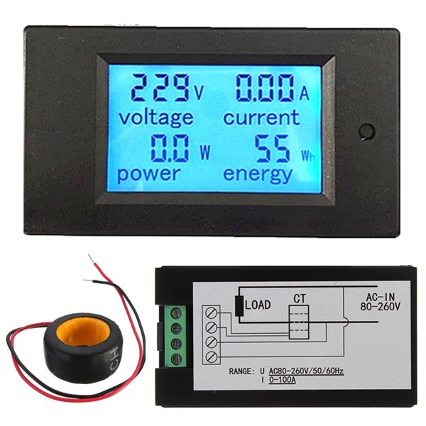 Volmètre ampèremètre Wattmètre 260v 100amp
-
32,00 €
Volmètre ampèremètre Wattmètre 260v 100amp
-
32,00 €
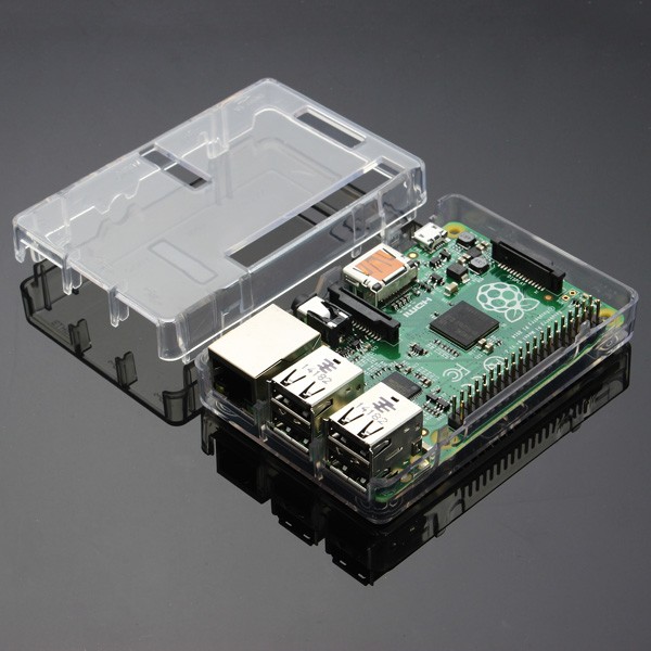 BOITIER TRANSPARENT RASPBERRY PI3
-
3,00 €
BOITIER TRANSPARENT RASPBERRY PI3
-
3,00 €
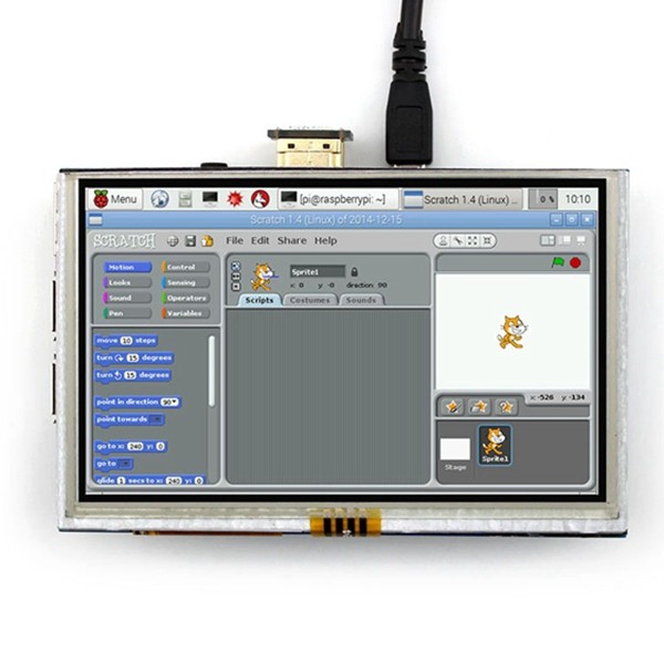 ECRAN TACTILE 5" RASPBERRY PI2 PI3 B, B+, A+, B
-
59,00 €
ECRAN TACTILE 5" RASPBERRY PI2 PI3 B, B+, A+, B
-
59,00 €
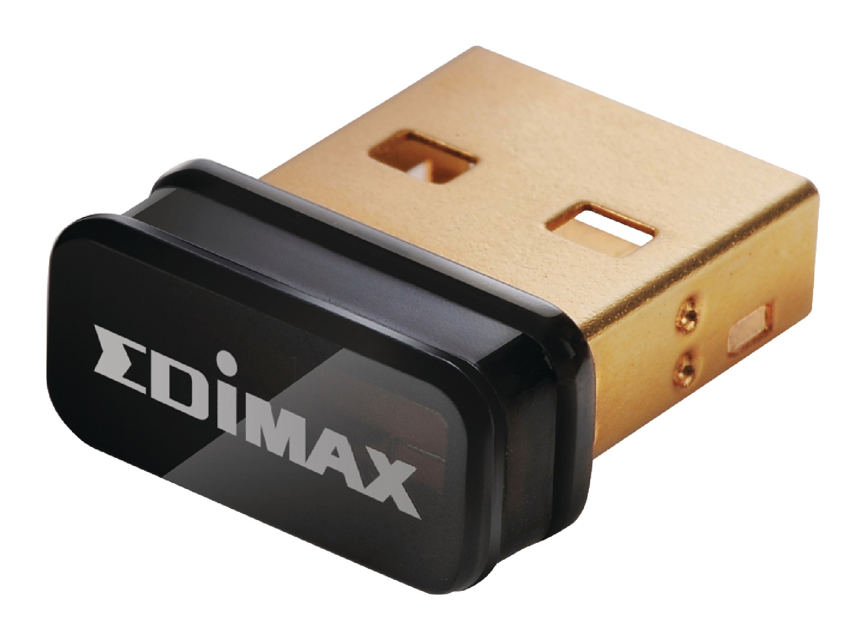 Clef usb Nano sans fil 150Mbps 802.11b/g/n raspberry
-
13,90 €
MODULE RASPBERRY PI 4 2GO -MOD B QUAD CORE-A72 1.5GHz-40,83 €
Clef usb Nano sans fil 150Mbps 802.11b/g/n raspberry
-
13,90 €
MODULE RASPBERRY PI 4 2GO -MOD B QUAD CORE-A72 1.5GHz-40,83 €
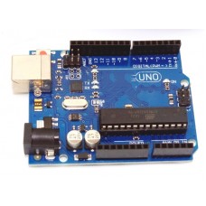 MODULE UNO REV3 ARDUINO 215600-12,50 €
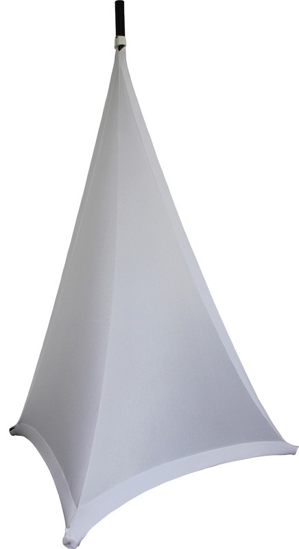
 HOUSSE POUR ENCEINTE PORT12-VHF-BT
-
29,00 €
HOUSSE POUR ENCEINTE PORT12-VHF-BT
-
29,00 €
 HOUSSE POUR ENCEINTE PORT10-VHF-BT
-
29,00 €
HOUSSE POUR ENCEINTE PORT10-VHF-BT
-
29,00 €
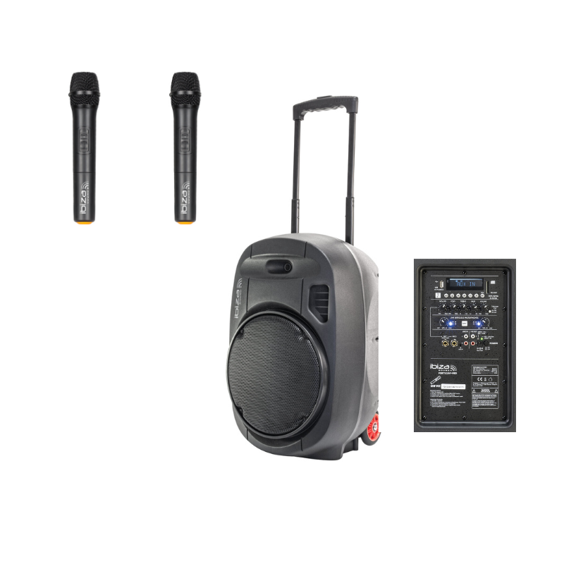
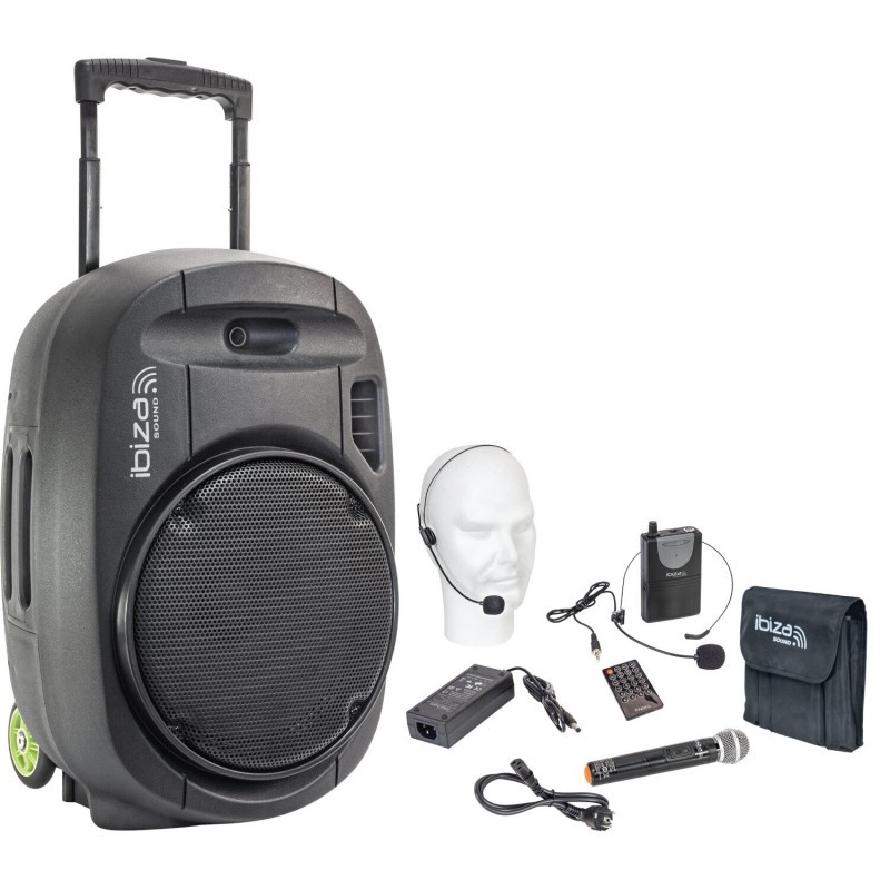
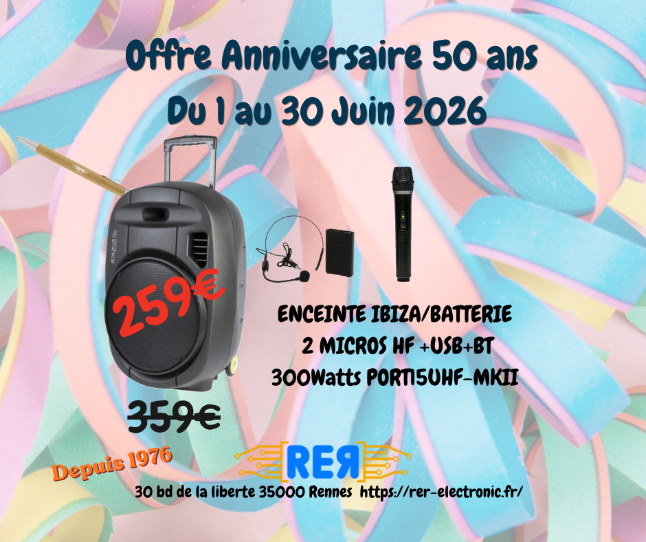 ENCEINTE AMPLIFIE 200W IBIZA USB+2 MICRO HF+BLUETOOTH
-
259,00 €
ENCEINTE AMPLIFIE 200W IBIZA USB+2 MICRO HF+BLUETOOTH
-
259,00 €
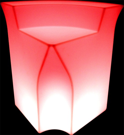
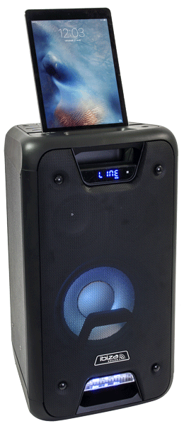 ENCEINTE FREESOUND 300W AVEC EFFET LEDS
-
149,00 €
ENCEINTE FREESOUND 300W AVEC EFFET LEDS
-
149,00 €
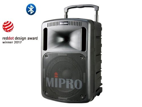 ENCEINTE MIPRO 276W/CD +USB +1MICRO HF MAIN
-
999,90 €
ENCEINTE MIPRO 276W/CD +USB +1MICRO HF MAIN
-
999,90 €
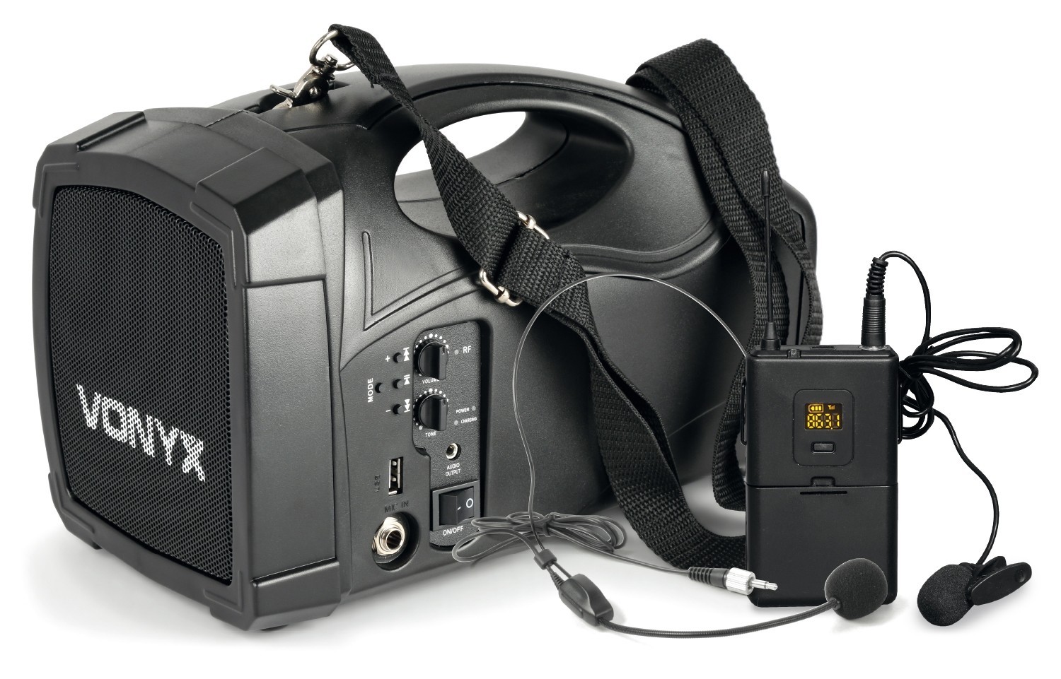 PORTE VOIX NOMADE VONYX MICRO SERRE TÈTE
-
259,00 €
PORTE VOIX NOMADE VONYX MICRO SERRE TÈTE
-
259,00 €
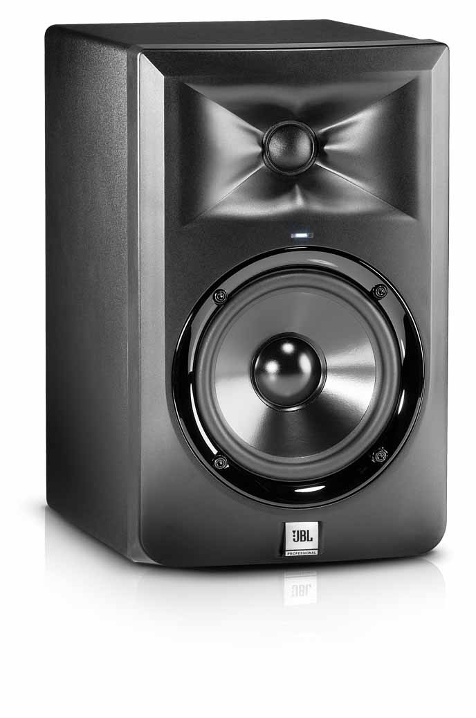 MONITEUR STUDIO JBL 305PMKII 5POUCES
-
155,00 €
MONITEUR STUDIO JBL 305PMKII 5POUCES
-
155,00 €
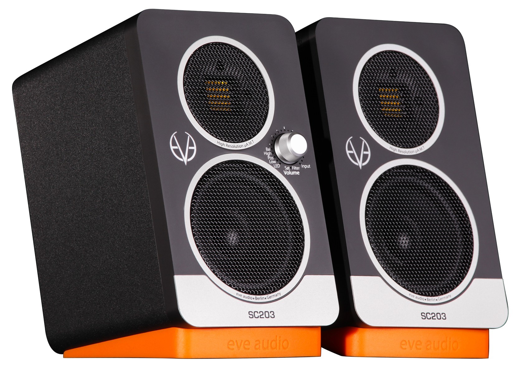 ENCEINTE MONITORING SC203 EVE AUDIO la paire
-
399,00 €
ENCEINTE MONITORING SC203 EVE AUDIO la paire
-
399,00 €
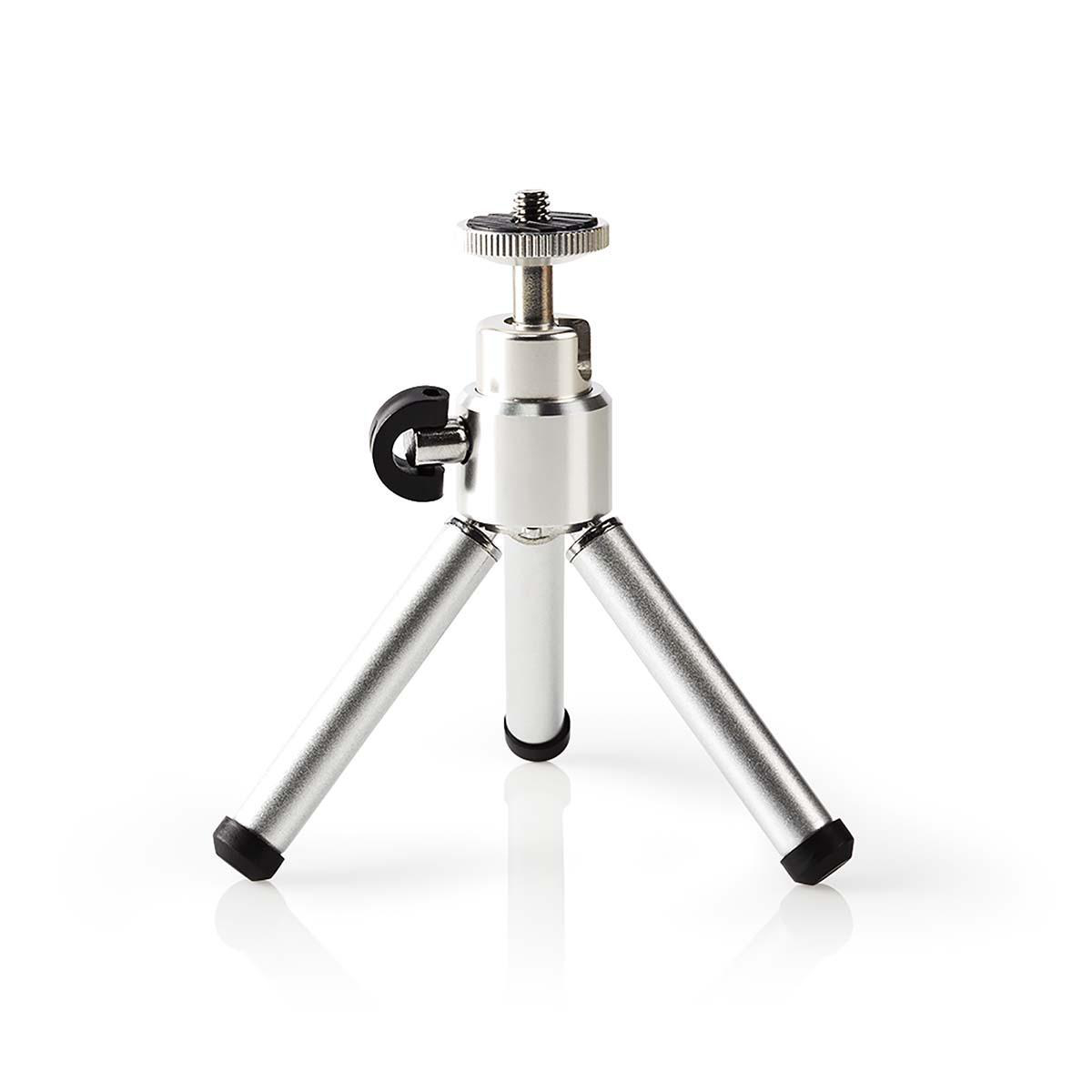
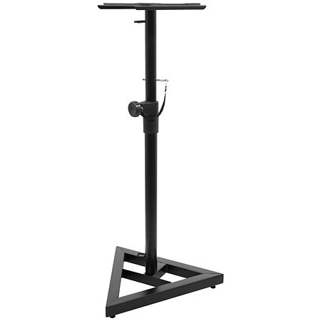 PIED MONITORING STUDIO LA PAIRE
-
79,00 €
PIED MONITORING STUDIO LA PAIRE
-
79,00 €
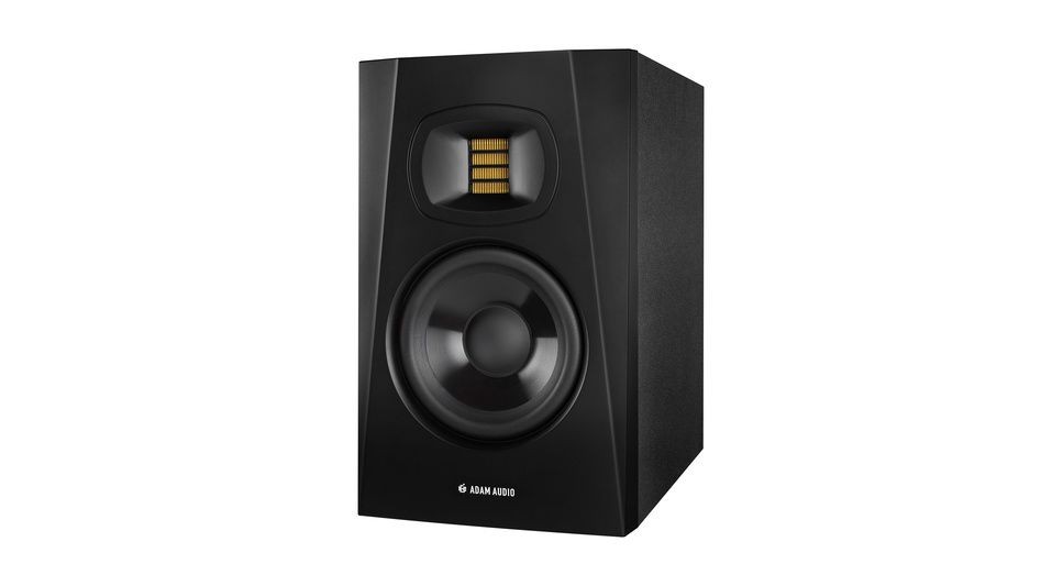 MONITOR T5V ADAM AUDIO LA PAIRE
-
369,00 €
MONITOR T5V ADAM AUDIO LA PAIRE
-
369,00 €
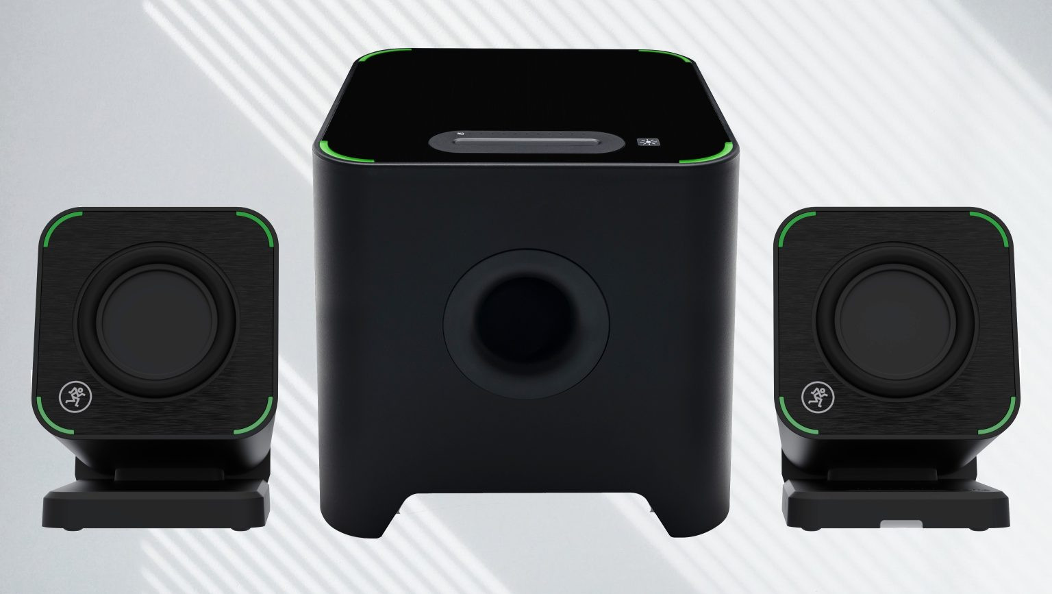
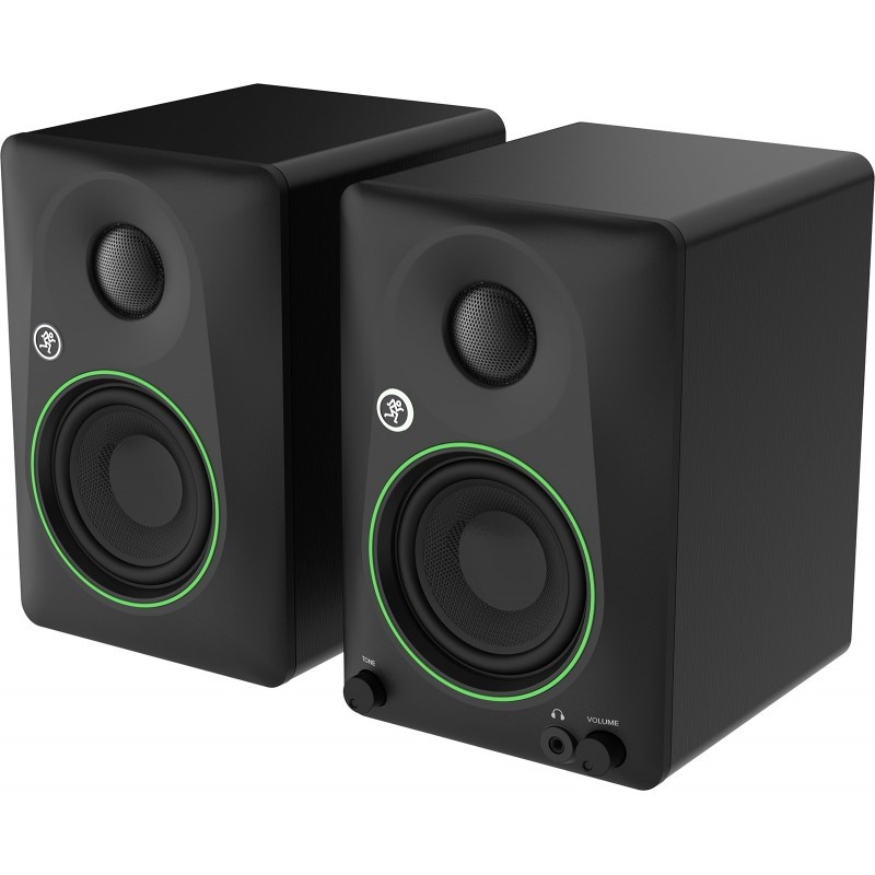 ENCEINTES MONITORING CR45BT BLUETOOTH MACKIE LA PAIRE
-
179,00 €
ENCEINTES MONITORING CR45BT BLUETOOTH MACKIE LA PAIRE
-
179,00 €
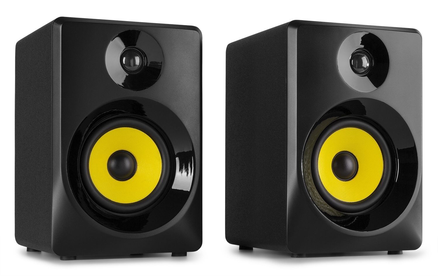 MONITEURS VONYX 4 POUCES 50W LA PAIRE
-
159,00 €
MONITEURS VONYX 4 POUCES 50W LA PAIRE
-
159,00 €
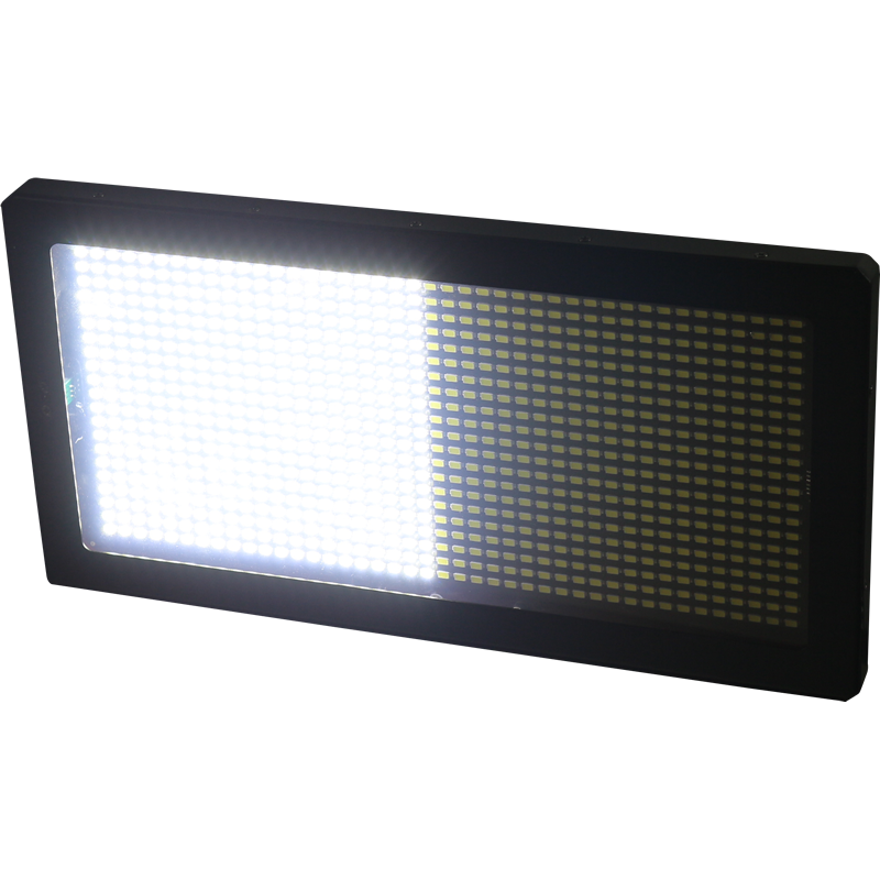
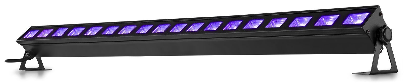 BARRE LED UV 1MT LUMIERE NOIRE
-
79,00 €
BARRE LED UV 1MT LUMIERE NOIRE
-
79,00 €
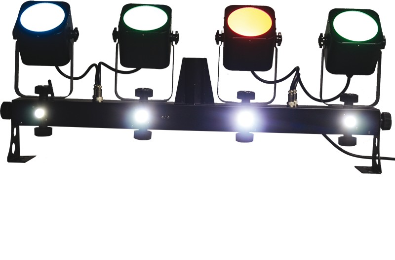
 ENSEMBLE DE 4 PAR A LED AVEC SUPPORT ET TELECOMMANDE
-
75,00 €
ENSEMBLE DE 4 PAR A LED AVEC SUPPORT ET TELECOMMANDE
-
75,00 €
 BARRE DE LUMIERE DMX AUTONOME 4-en-1
-
359,00 €
BARRE DE LUMIERE DMX AUTONOME 4-en-1
-
359,00 €
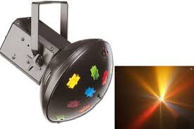
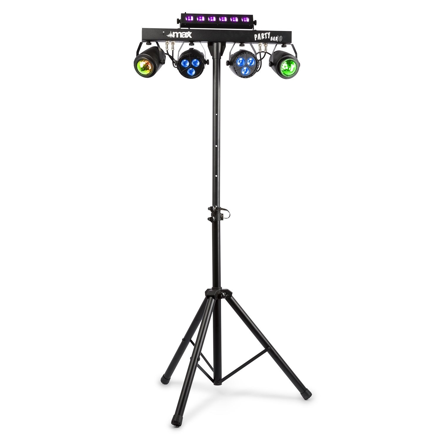
 JEU DE LUMIÈRE PARTYBAR10, BARRE ÉQUIPÉE DE JELLY MOON 2 X, PAR 2 X ET UV/STROBE
-
299,00 €
JEU DE LUMIÈRE PARTYBAR10, BARRE ÉQUIPÉE DE JELLY MOON 2 X, PAR 2 X ET UV/STROBE
-
299,00 €
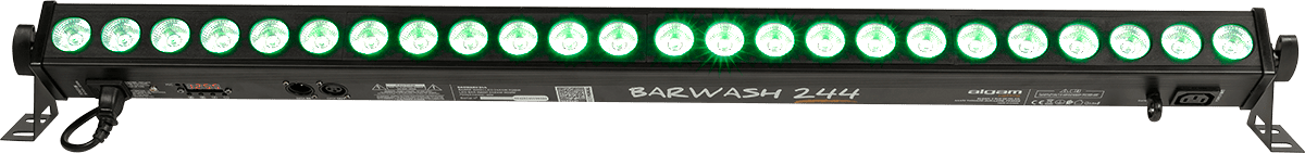 BARRE LED 24 X 4W RGBW + TLC 1060 x 64 x 104mm
-
119,00 €
BARRE LED 24 X 4W RGBW + TLC 1060 x 64 x 104mm
-
119,00 €
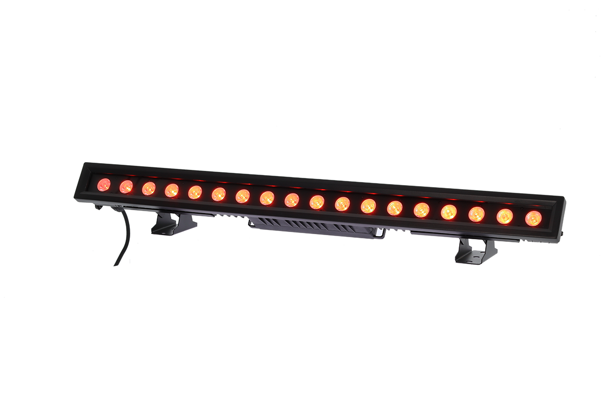 Barre LED 18 X 12W RGBW 1Mt PIX IP65 Algam lighting
-
389,00 €
Barre LED 18 X 12W RGBW 1Mt PIX IP65 Algam lighting
-
389,00 €
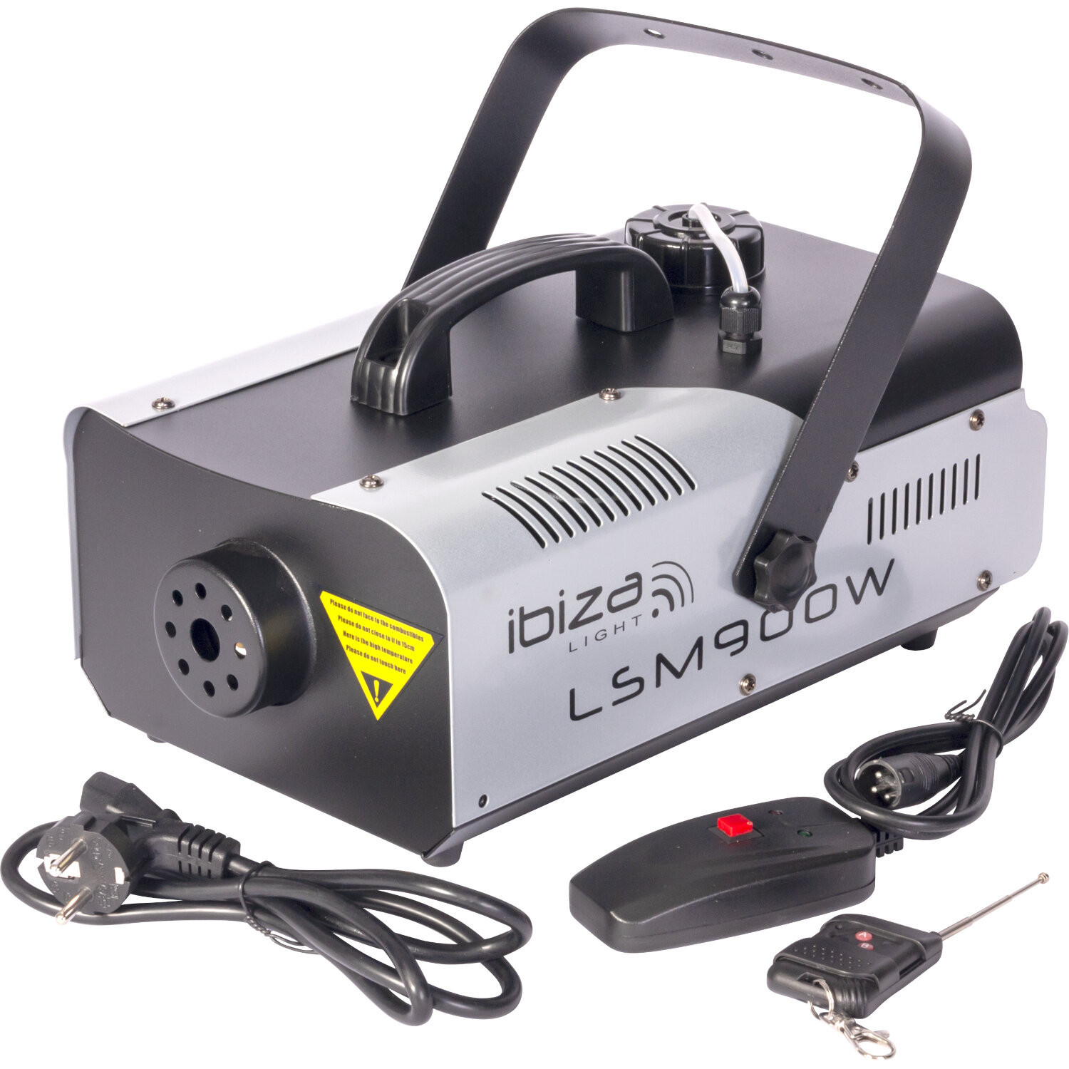 MACHINE A FUMEE 900WATT IBIZA TELECOMMANDE SANS FIL
-
89,00 €
MACHINE A FUMEE 900WATT IBIZA TELECOMMANDE SANS FIL
-
89,00 €
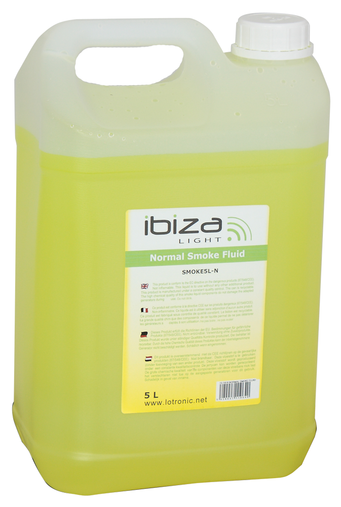
 LIQUIDE MACHINE A BROUILLARD 5 LITRES
-
29,00 €
LIQUIDE MACHINE A BROUILLARD 5 LITRES
-
29,00 €
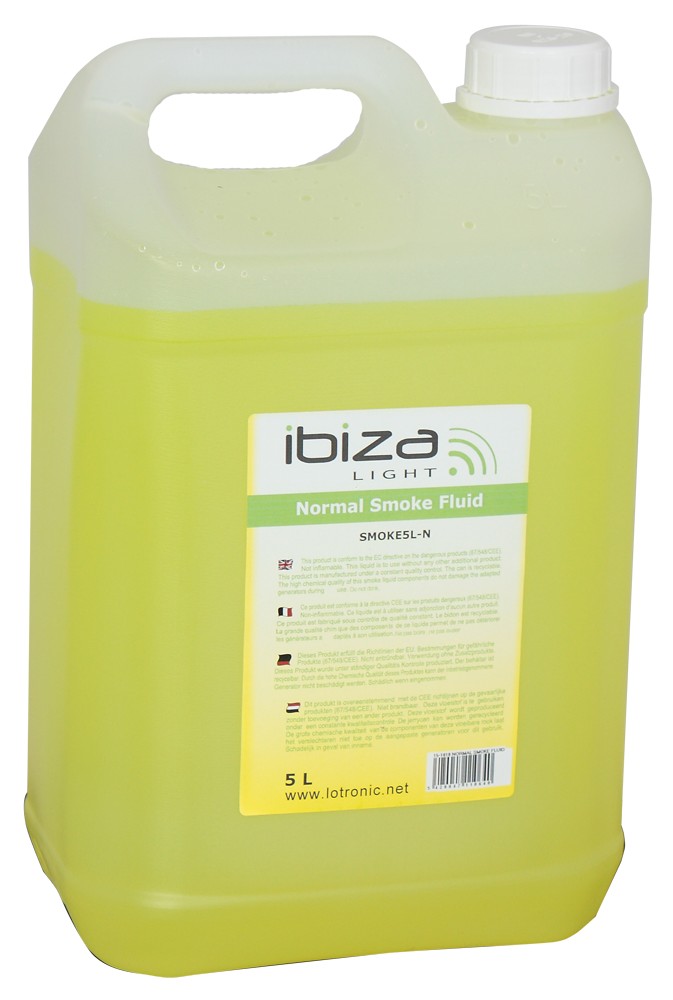
 LIQUIDE A FUMEE 5L STANDARD
-
14,50 €
LIQUIDE A FUMEE 5L STANDARD
-
14,50 €
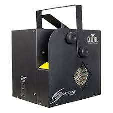
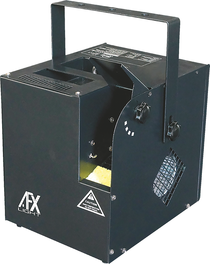 MACHINE A BROUILLARD 700W AVEC PROGRAMMATEUR
-
379,00 €
MACHINE A BROUILLARD 700W AVEC PROGRAMMATEUR
-
379,00 €
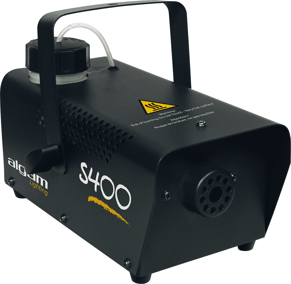 MACHINE A FUMEE 400W MINI S400 ALGAM LIGHTING
-
49,00 €
MACHINE A FUMEE 400W MINI S400 ALGAM LIGHTING
-
49,00 €
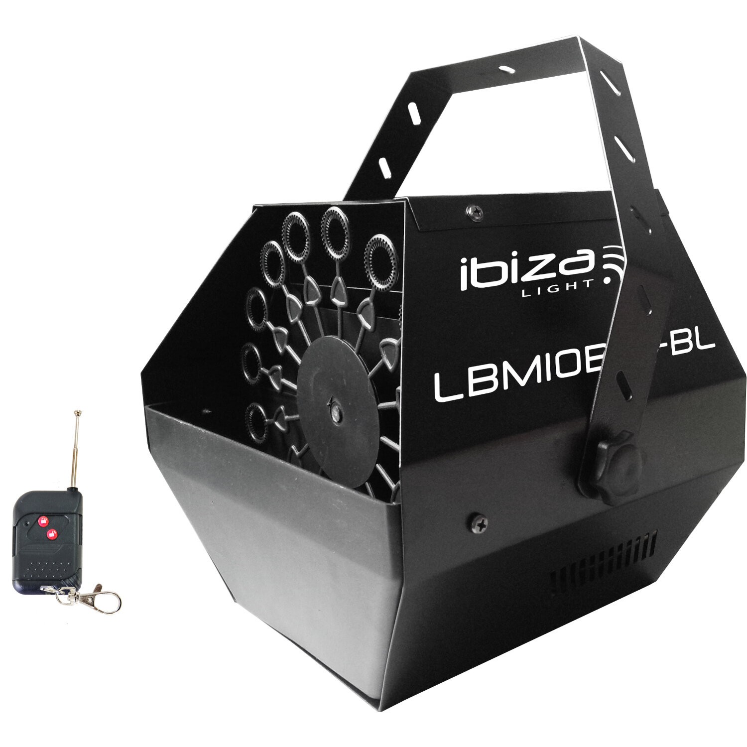 MACHINE A BULLES RECHARGEABLE SUR BATTERIE
-
69,90 €
MACHINE A BULLES RECHARGEABLE SUR BATTERIE
-
69,90 €
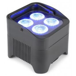 Projecteur PAR 4 x 10 W AUTONOME
-
199,00 €
Projecteur PAR 4 x 10 W AUTONOME
-
199,00 €
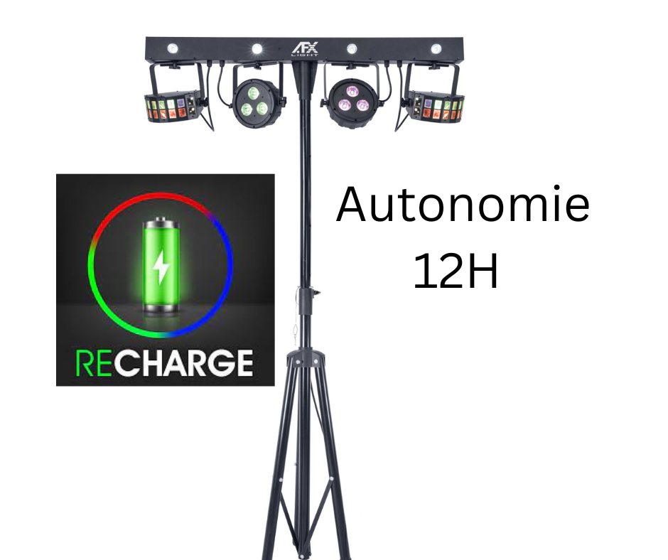
 Projecteur COMBO-BAR AFX
-
223,20 €
Projecteur COMBO-BAR AFX
-
223,20 €
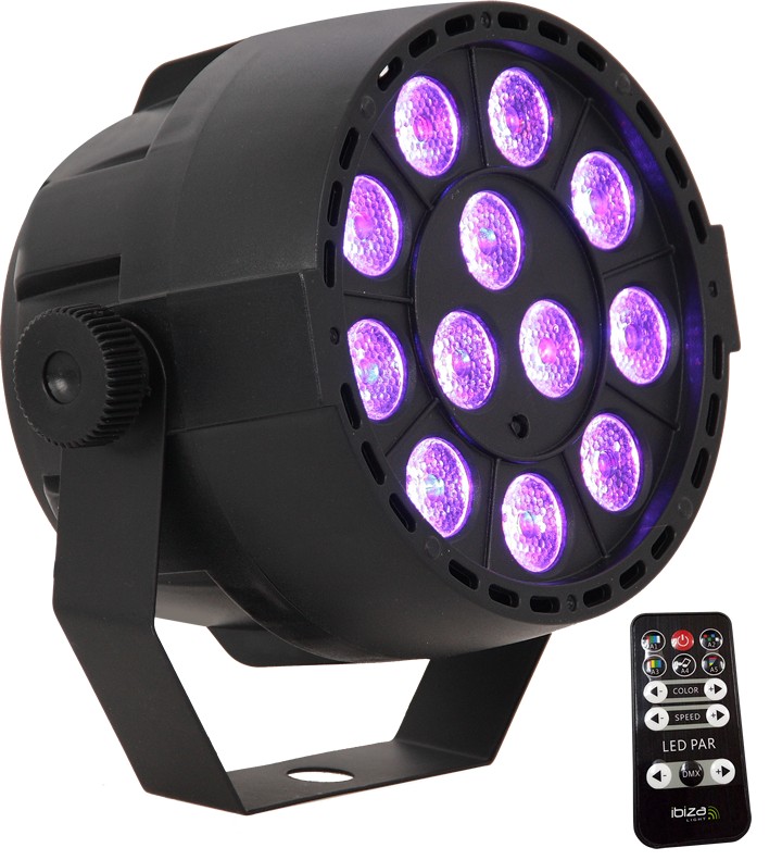 PROJECTEUR PAR A LED 12 X 3W RVB 3-EN-1
-
39,00 €
PROJECTEUR PAR A LED 12 X 3W RVB 3-EN-1
-
39,00 €
 PROJECTEUR BRITEQ RVB + LAMPE 575W AVEC PIED CAB200 OFFERT
-
679,50 €
ENSEMBLE DE 4 PAR A LED AVEC SUPPORT ET TELECOMMANDE
-
75,00 €
PROJECTEUR BRITEQ RVB + LAMPE 575W AVEC PIED CAB200 OFFERT
-
679,50 €
ENSEMBLE DE 4 PAR A LED AVEC SUPPORT ET TELECOMMANDE
-
75,00 €
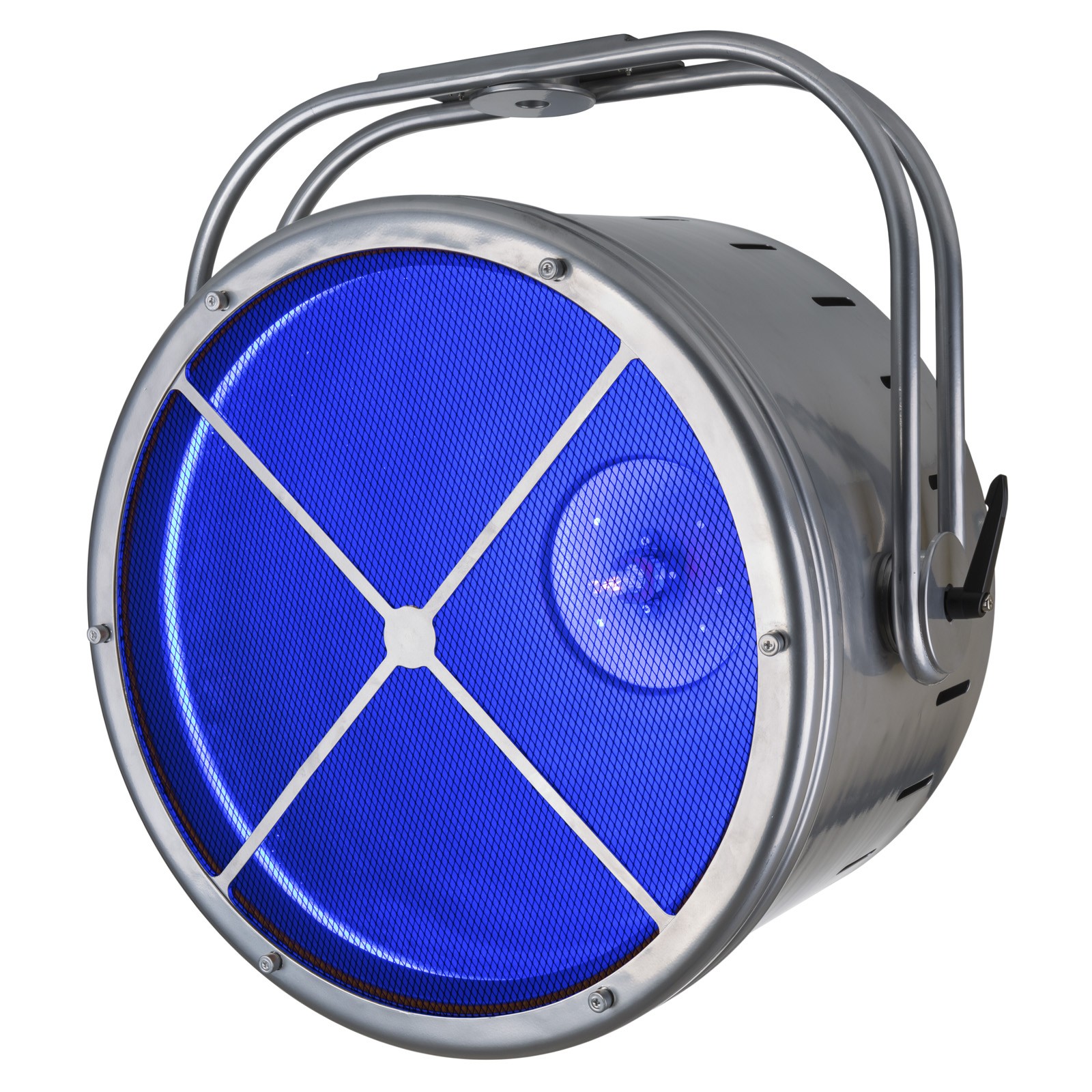
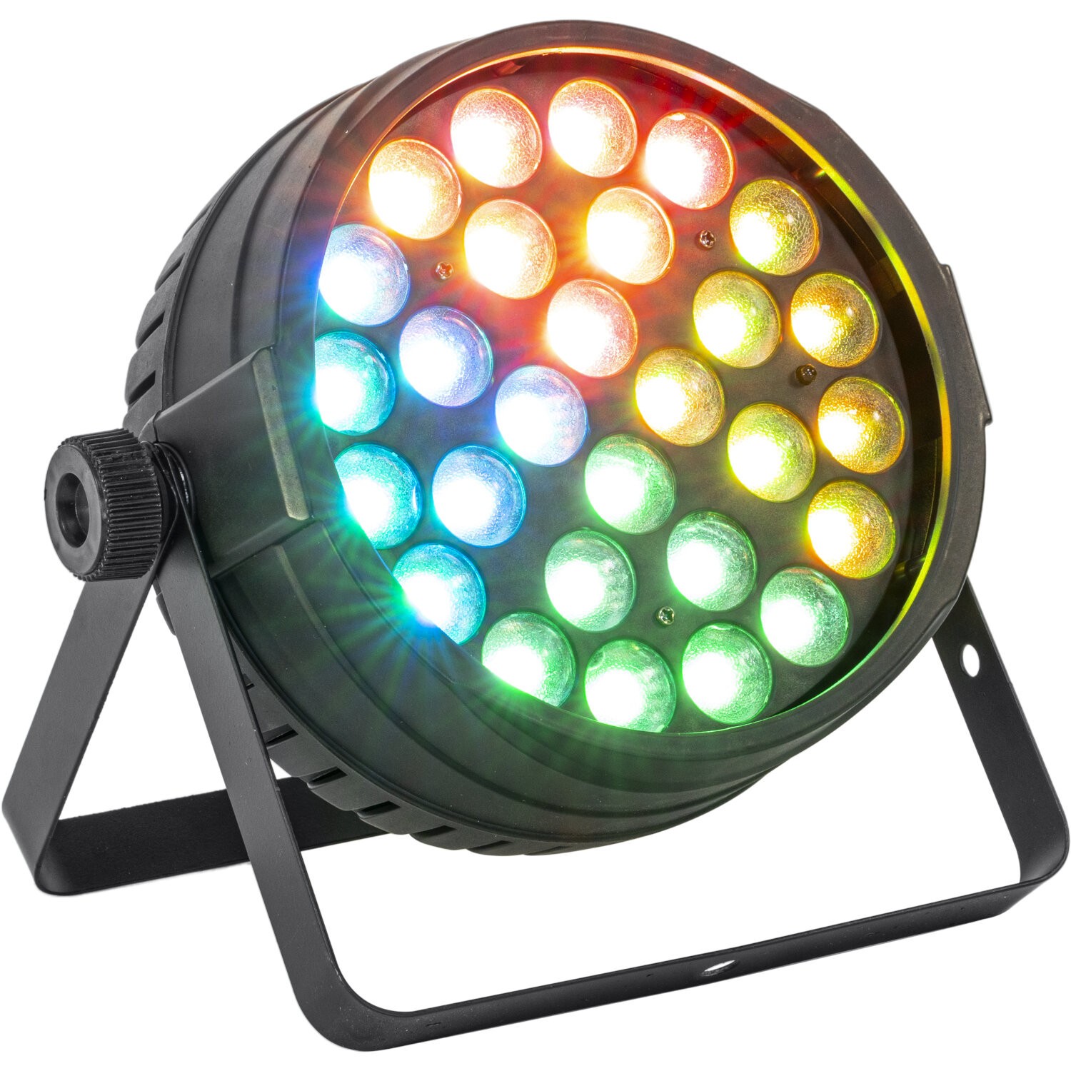 PROJECTEUR PAR A LED RGBW 28 x 10W AVEC ZOOM PAR QUARTIERS
-
299,00 €
PROJECTEUR PAR A LED RGBW 28 x 10W AVEC ZOOM PAR QUARTIERS
-
299,00 €
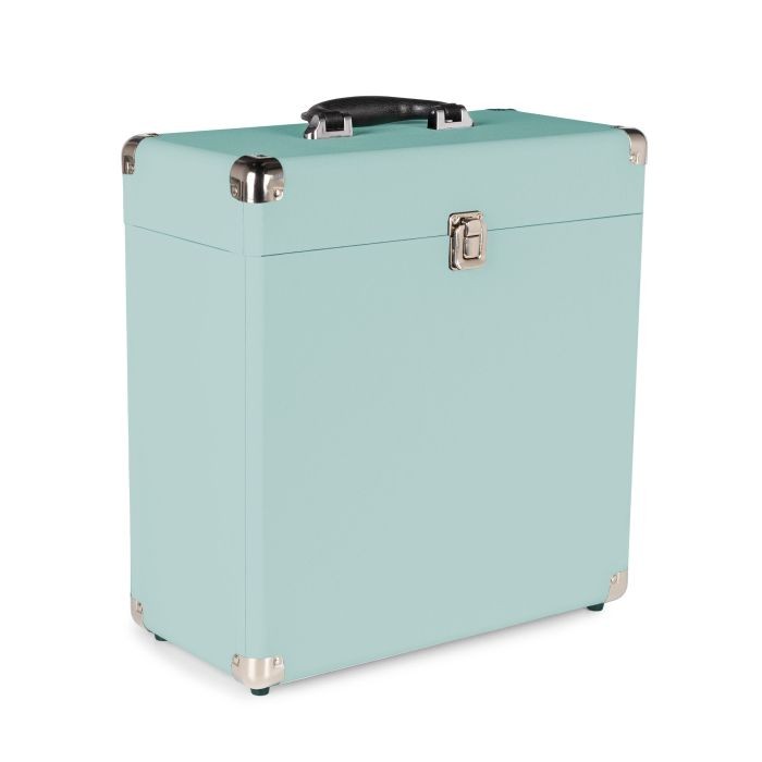
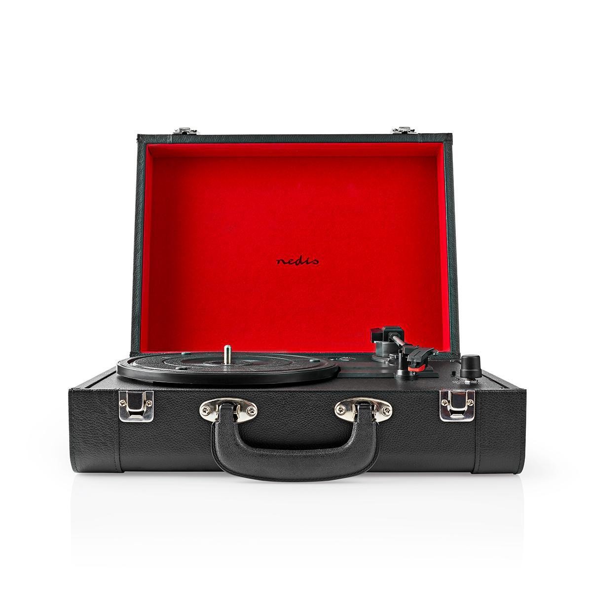 PLATINE VINYLE VALISE RETRO RECHARGEABLE
-
89,00 €
PLATINE VINYLE VALISE RETRO RECHARGEABLE
-
89,00 €
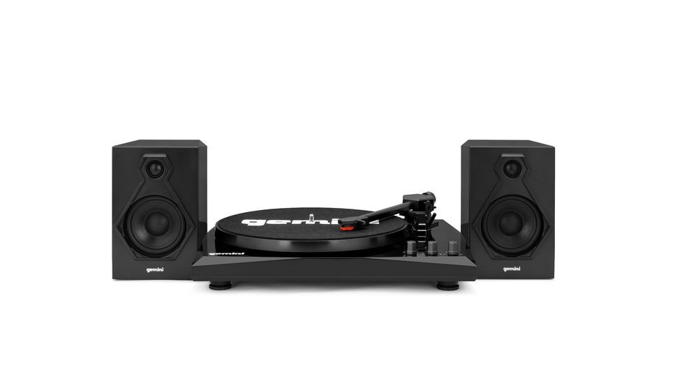 PLATINE VINYLE BLUETOOTH + ENCEINTES GEMINI TT-900
-
99,00 €
PLATINE VINYLE BLUETOOTH + ENCEINTES GEMINI TT-900
-
99,00 €
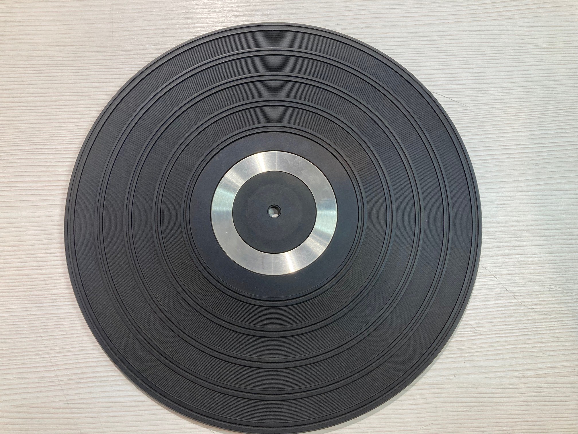 Couvre plateau caoutchouc (occasion)
-
29,00 €
Couvre plateau caoutchouc (occasion)
-
29,00 €
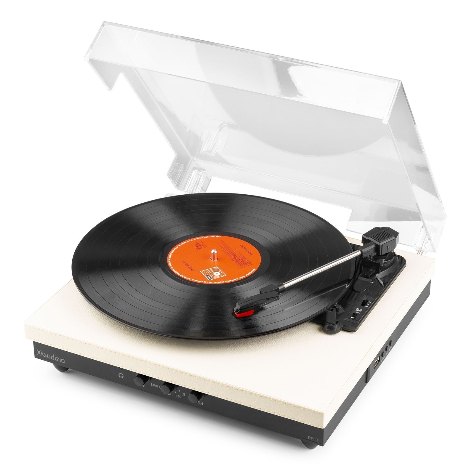 PLATINE VINYLE USB EMETTEUR BLUETOOTH
-
139,90 €
PLATINE VINYLE USB EMETTEUR BLUETOOTH
-
139,90 €
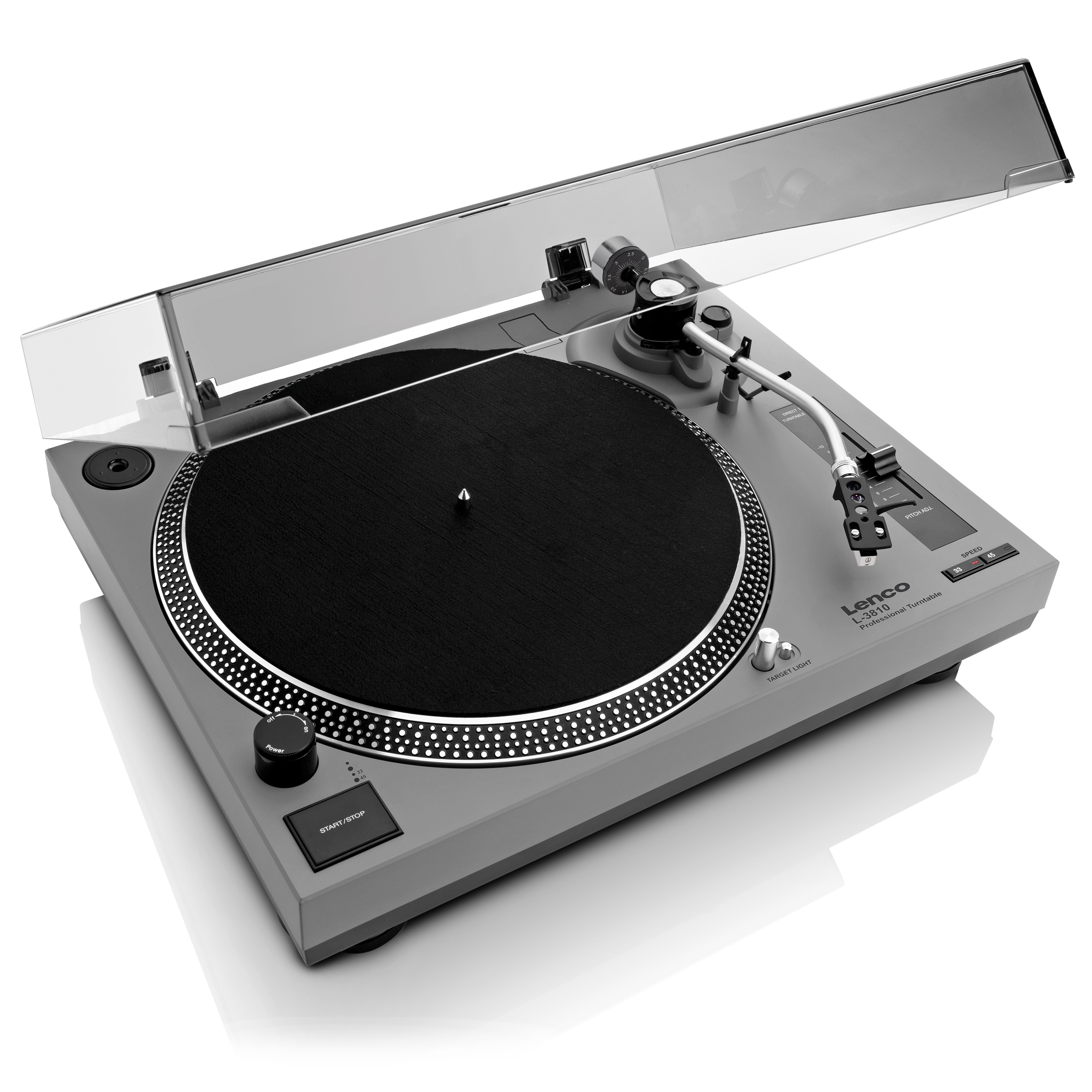
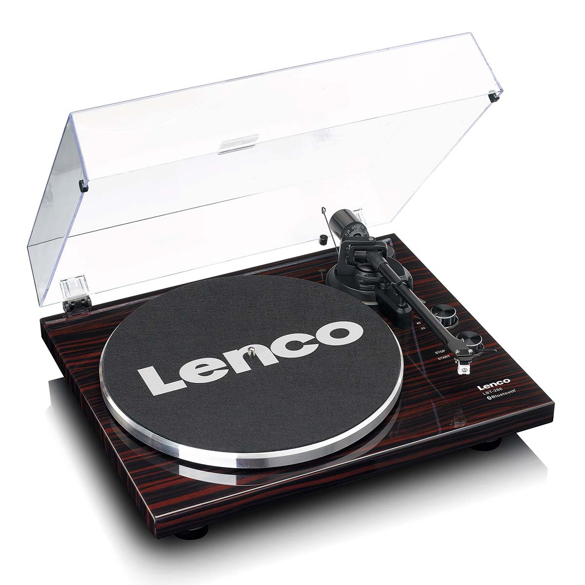 PLATINE DISQUE LENCO BRUN FONCE TRANSMISSION BLUETOOTH
-
259,00 €
PLATINE DISQUE LENCO BRUN FONCE TRANSMISSION BLUETOOTH
-
259,00 €
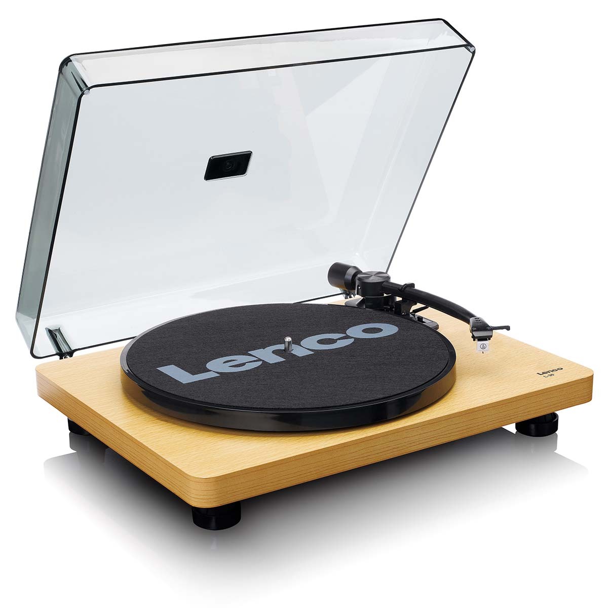 PLATINE DISQUE LENCO BOIS CLAIR ARRET AUTOMATIQUE
-
149,00 €
PLATINE DISQUE LENCO BOIS CLAIR ARRET AUTOMATIQUE
-
149,00 €
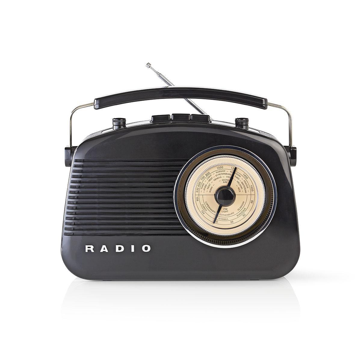 Radio AM/FM design rétro noir
-
49,00 €
Radio AM/FM design rétro noir
-
49,00 €
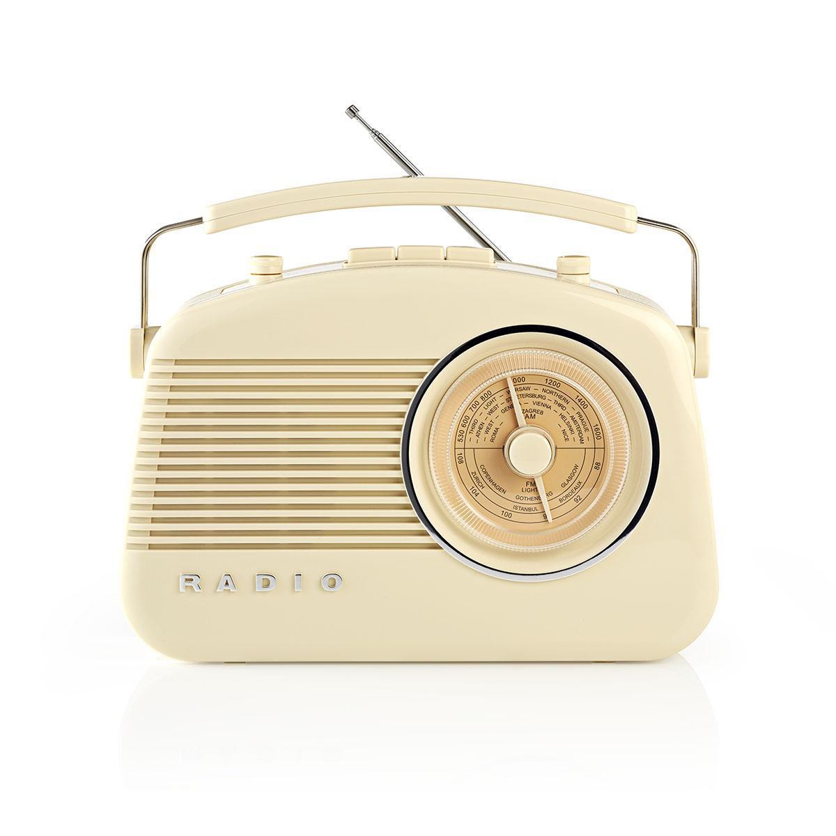 RADIO RETRO BLANC IVOIRE
-
49,00 €
RADIO RETRO BLANC IVOIRE
-
49,00 €
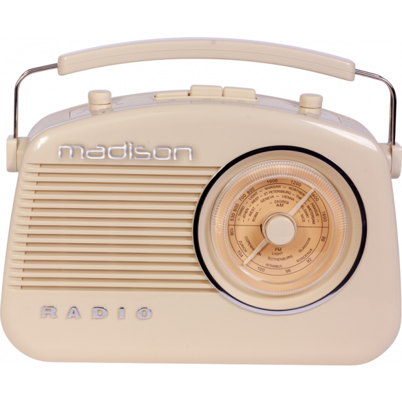 RADIO RETRO BLANC IVOIRE BLUETOOTH MAD-VR60
-
69,00 €
RADIO RETRO BLANC IVOIRE BLUETOOTH MAD-VR60
-
69,00 €
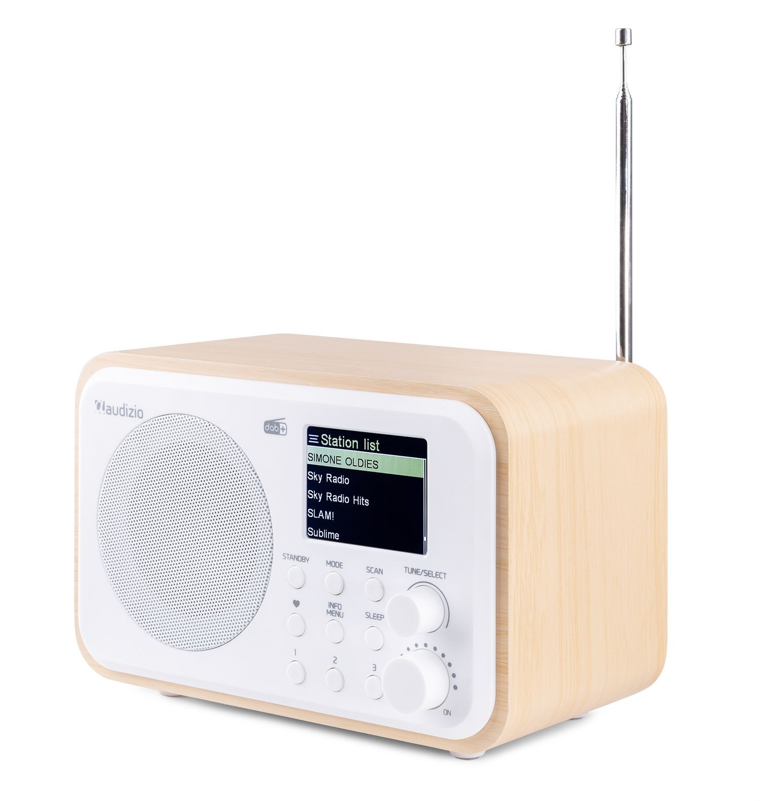 RADIO DAB+ MILAN SUR BATTERIE, COULEUR BOIS CLAIR
-
89,00 €
RADIO DAB+ MILAN SUR BATTERIE, COULEUR BOIS CLAIR
-
89,00 €
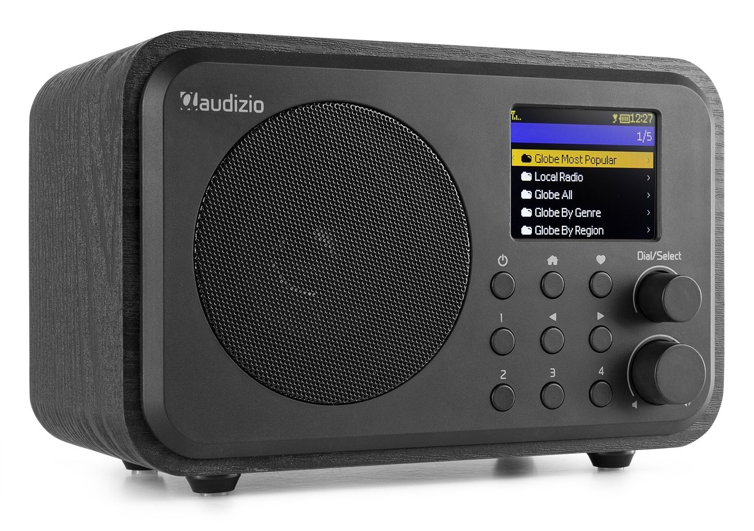 RADIO INTERNET WIFI VENICE SUR BATTERIE NOIRE
-
99,00 €
RADIO INTERNET WIFI VENICE SUR BATTERIE NOIRE
-
99,00 €
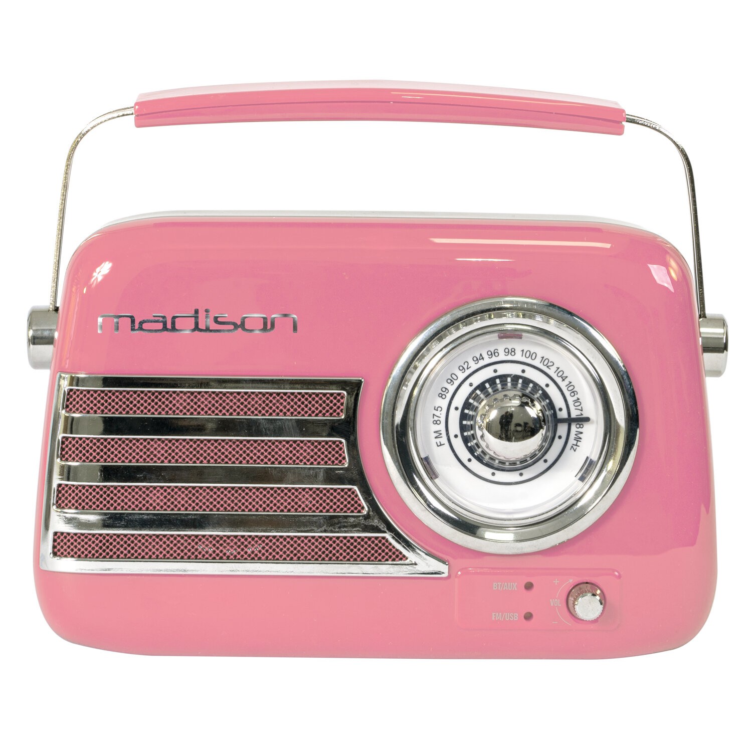 RADIO VINTAGE MADISON ROSE AVEC BLUETOOTH, USB & FM 30W
-
35,00 €
RADIO VINTAGE MADISON ROSE AVEC BLUETOOTH, USB & FM 30W
-
35,00 €
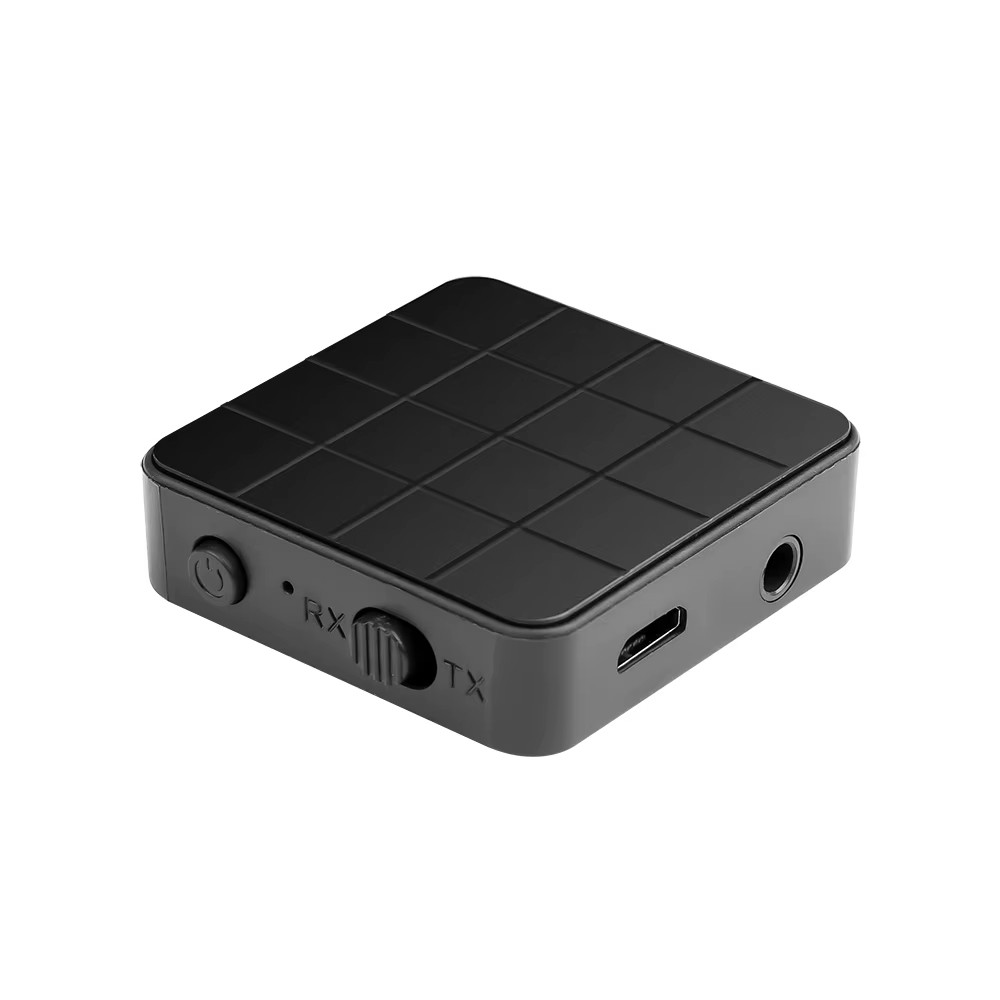 Récepteur Emeteur stéréo bluetooth® 10mts sur batterie
-
19,00 €
Récepteur Emeteur stéréo bluetooth® 10mts sur batterie
-
19,00 €
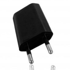 CHARGEUR USB SMARTPHONE 1Amp
-
8,00 €
ENCEINTE FREESOUND 300W AVEC EFFET LEDS
-
149,00 €
CHARGEUR USB SMARTPHONE 1Amp
-
8,00 €
ENCEINTE FREESOUND 300W AVEC EFFET LEDS
-
149,00 €
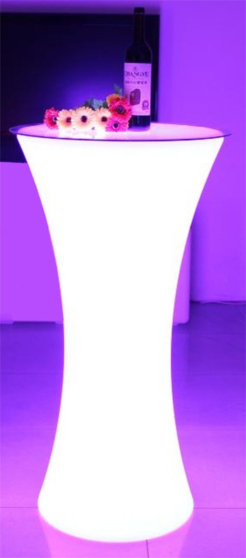
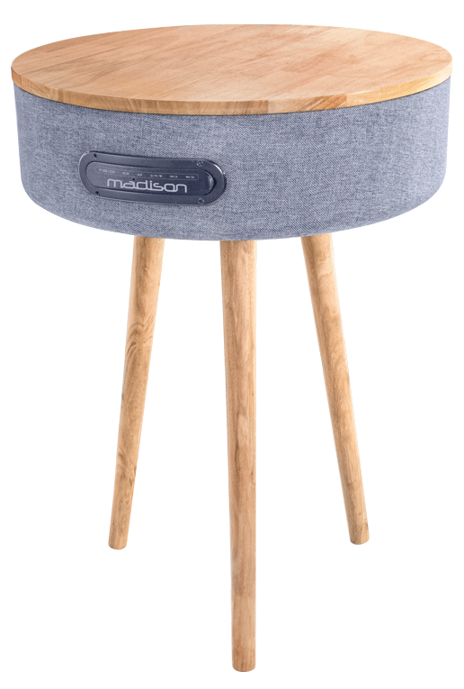 TABLE CONNECTEE AVEC ENCEINTE BLUETOOTH AVEC USB, MICRO-SD
-
119,00 €
RADIO INTERNET WIFI VENICE SUR BATTERIE NOIRE
-
99,00 €
TABLE CONNECTEE AVEC ENCEINTE BLUETOOTH AVEC USB, MICRO-SD
-
119,00 €
RADIO INTERNET WIFI VENICE SUR BATTERIE NOIRE
-
99,00 €
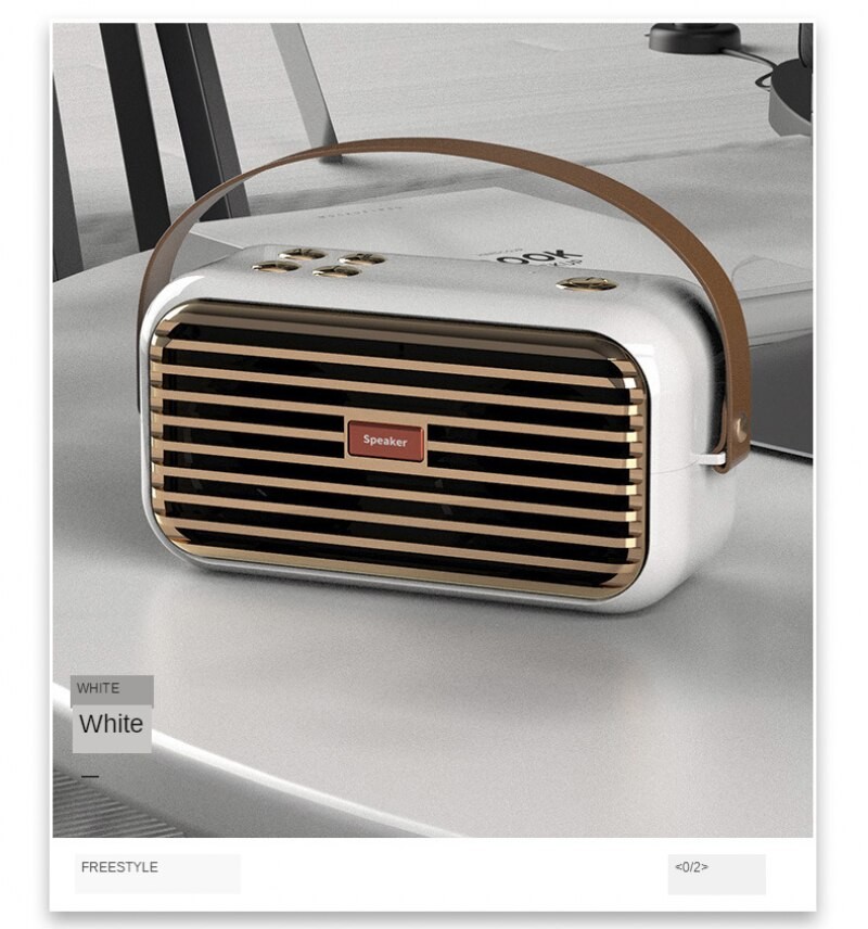 X7 ENCEINTE BLUETOOTH SON 3D TWS RADIO FM + AUX
-
45,00 €
X7 ENCEINTE BLUETOOTH SON 3D TWS RADIO FM + AUX
-
45,00 €
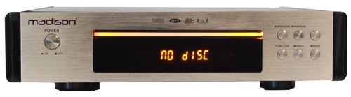 PLATINE CD TUNER FM MADISON
-
129,00 €
PLATINE CD TUNER FM MADISON
-
129,00 €
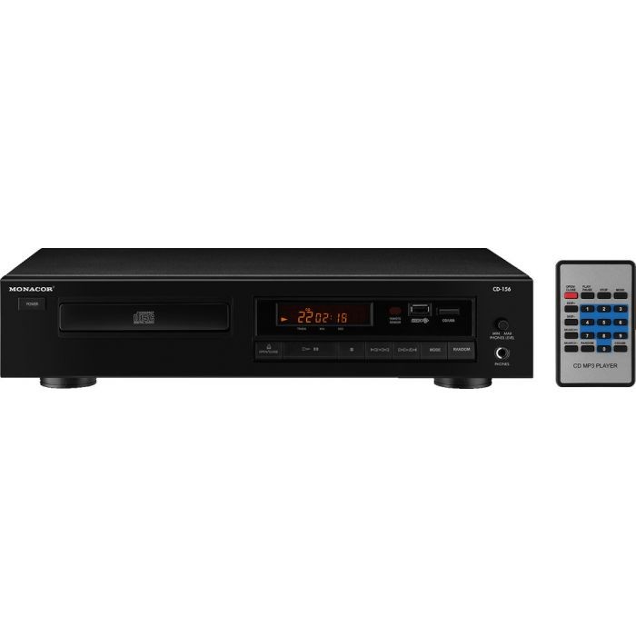 PLATINE CD STAGE LINE + USB CD-156
-
259,00 €
PLATINE CD STAGE LINE + USB CD-156
-
259,00 €
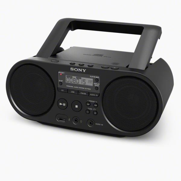 POSTE RADIO CD USB AUX SONY ZS-PS50
-
129,00 €
POSTE RADIO CD USB AUX SONY ZS-PS50
-
129,00 €
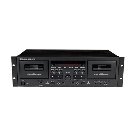 PLATINE CASSETTE TASCAM 202MKVII DOUBLE
-
589,00 €
PLATINE CASSETTE TASCAM 202MKVII DOUBLE
-
589,00 €
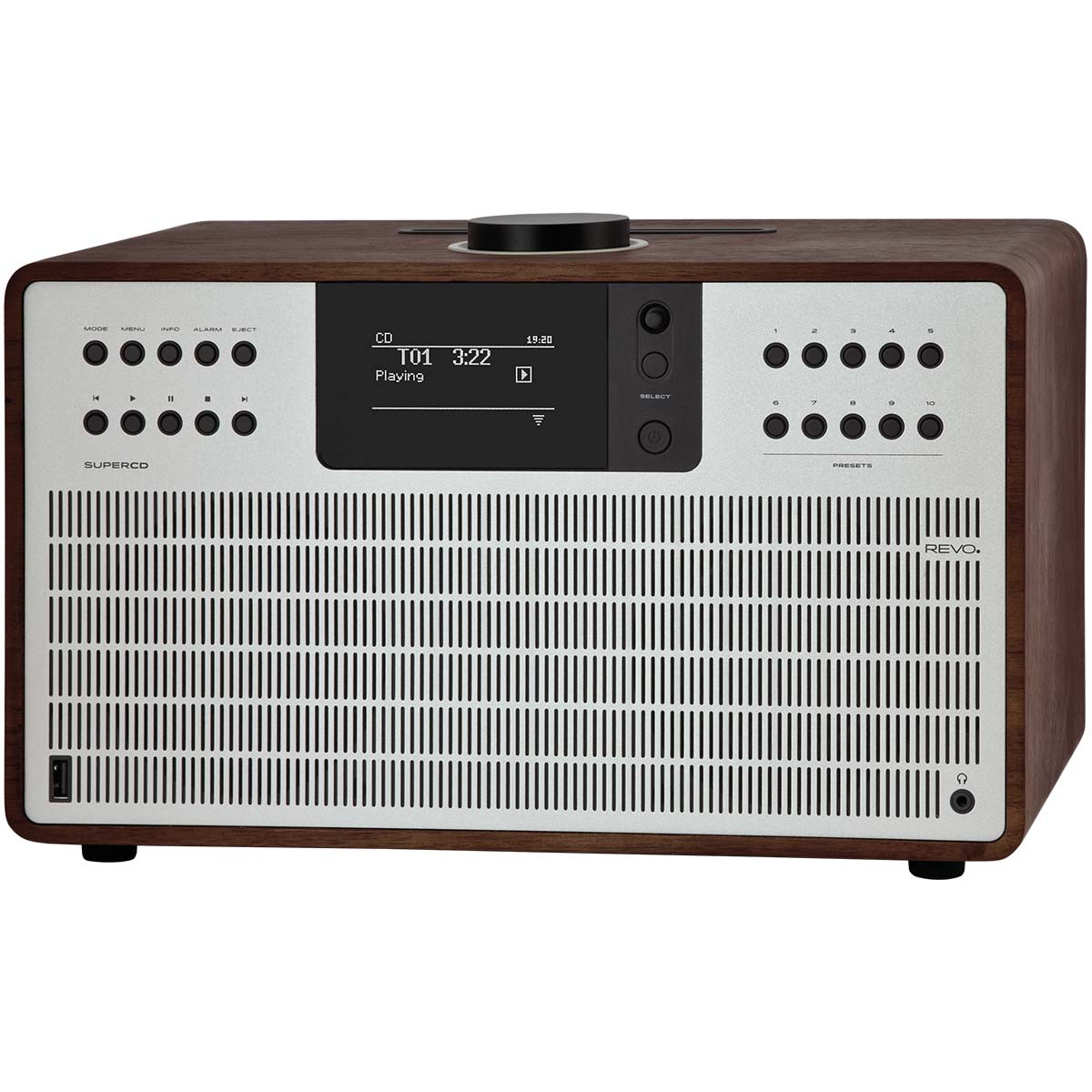 Revo Super CD ENCEINTE CD MULTIROOM DAB+ FM Bluetooth Noyer-Argenté
-
649,00 €
Revo Super CD ENCEINTE CD MULTIROOM DAB+ FM Bluetooth Noyer-Argenté
-
649,00 €
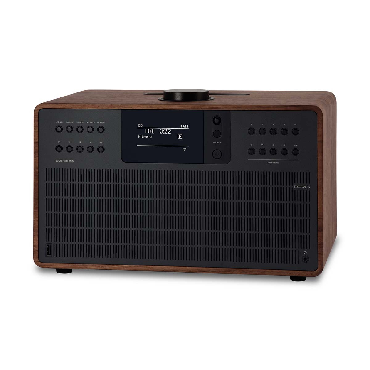 Revo Super CD ENCEINTE CD MULTIROOM DAB+ FM Bluetooth Noyer-Noir
-
649,00 €
Revo Super CD ENCEINTE CD MULTIROOM DAB+ FM Bluetooth Noyer-Noir
-
649,00 €
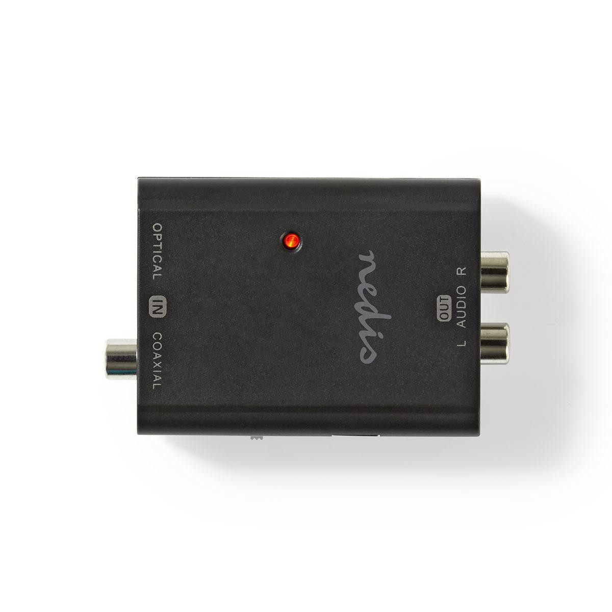
 RECEPTEUR BLUETOOTH SORTIE OPT + ANALOGIQUE
-
59,00 €
RECEPTEUR BLUETOOTH SORTIE OPT + ANALOGIQUE
-
59,00 €
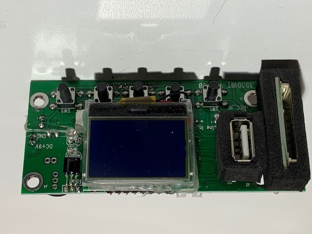 CARTE BLUETOOTH IBIZA SERIE PORT10 12 15 85 VHF
-
59,90 €
CARTE BLUETOOTH IBIZA SERIE PORT10 12 15 85 VHF
-
59,90 €
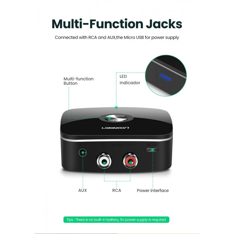
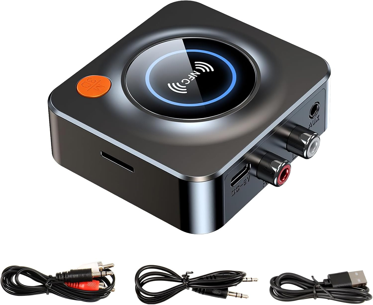 RECEPTEUR BLUETOOTH 5.3 SORTIE JACK ET RCA
-
39,00 €
RECEPTEUR BLUETOOTH 5.3 SORTIE JACK ET RCA
-
39,00 €
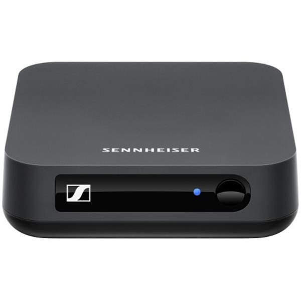 EMETTEUR BLUETOOTH APTX SENNHEISER
-
99,00 €
EMETTEUR BLUETOOTH APTX SENNHEISER
-
99,00 €
 RECEPTEUR BLUETOOTH APTX 5.4 SORTIE RCA
-
59,00 €
RECEPTEUR BLUETOOTH APTX 5.4 SORTIE RCA
-
59,00 €
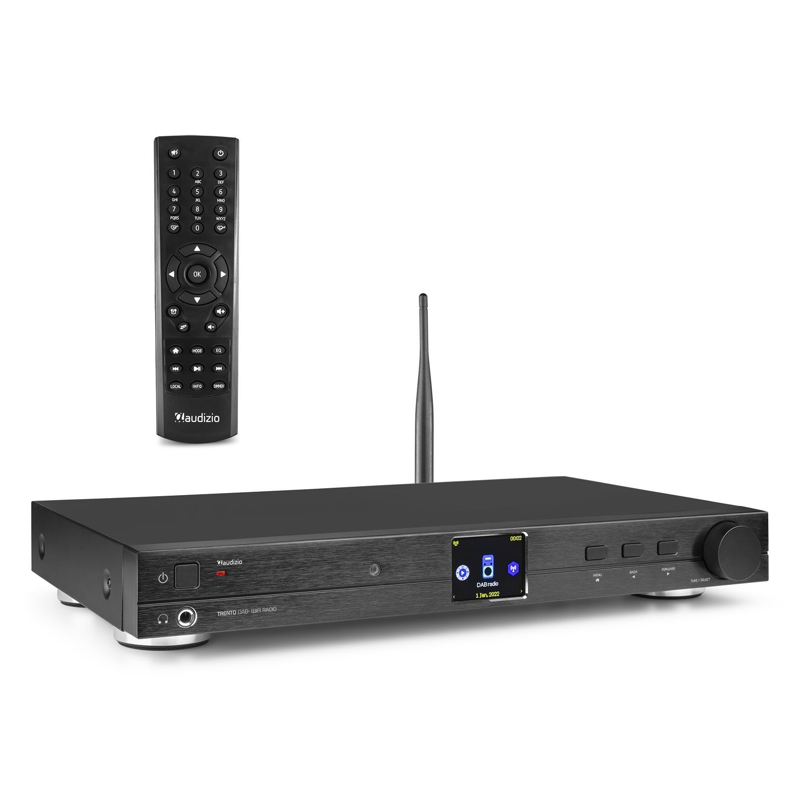 TUNER DAB+ / FM / WIFI / RJ45 / Bluetooth
-
259,00 €
TUNER DAB+ / FM / WIFI / RJ45 / Bluetooth
-
259,00 €
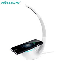 CHARGEUR NILLKIN SANS FIL POUR SMARTPHONE + LAMPE
-
59,00 €
CHARGEUR NILLKIN SANS FIL POUR SMARTPHONE + LAMPE
-
59,00 €
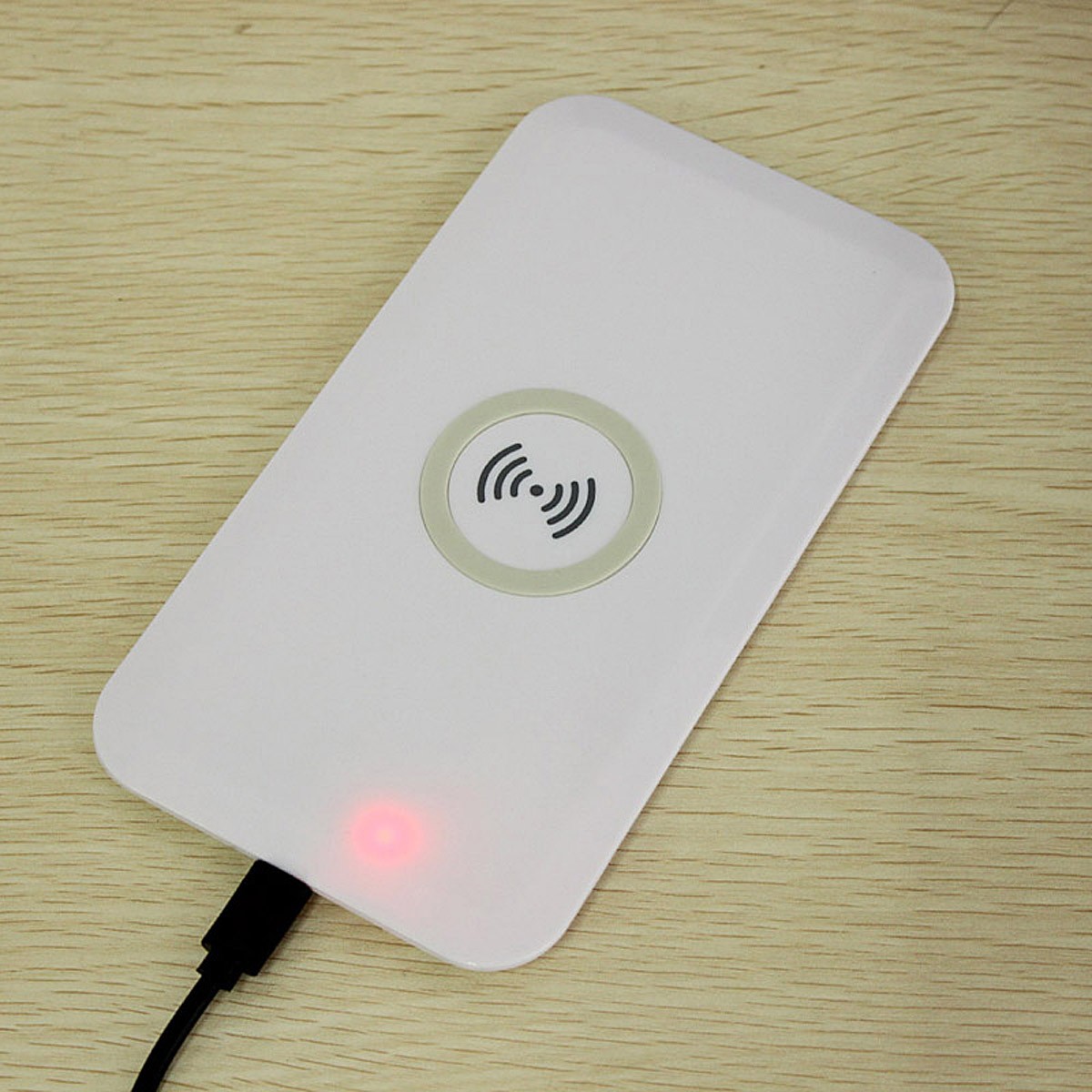 TRANSMETTEUR DE CHARGE SANS FIL SMARTPHONE QI NFC
-
19,90 €
TRANSMETTEUR DE CHARGE SANS FIL SMARTPHONE QI NFC
-
19,90 €
 TRANSMETTEUR DE CHARGE SANS FIL SMARTPHONE QI NFC
-
9,90 €
TRANSMETTEUR DE CHARGE SANS FIL SMARTPHONE QI NFC
-
9,90 €
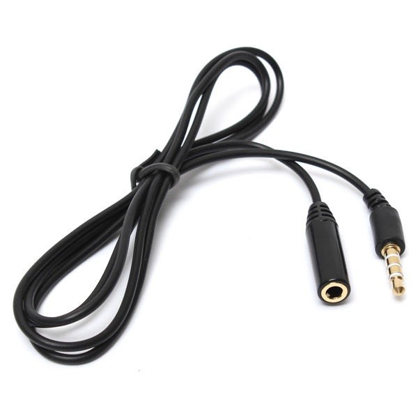 CORDON JACK 3.5 4CT M/F 1.20MTS
-
11,00 €
CORDON JACK 3.5 4CT M/F 1.20MTS
-
11,00 €
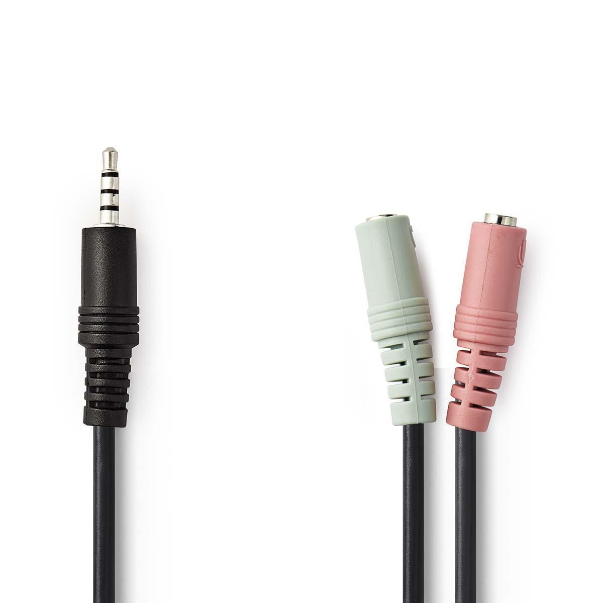 CORDON JACK Y 3.5 M 4P / VERS 2 JACK F
-
6,80 €
CORDON JACK Y 3.5 M 4P / VERS 2 JACK F
-
6,80 €
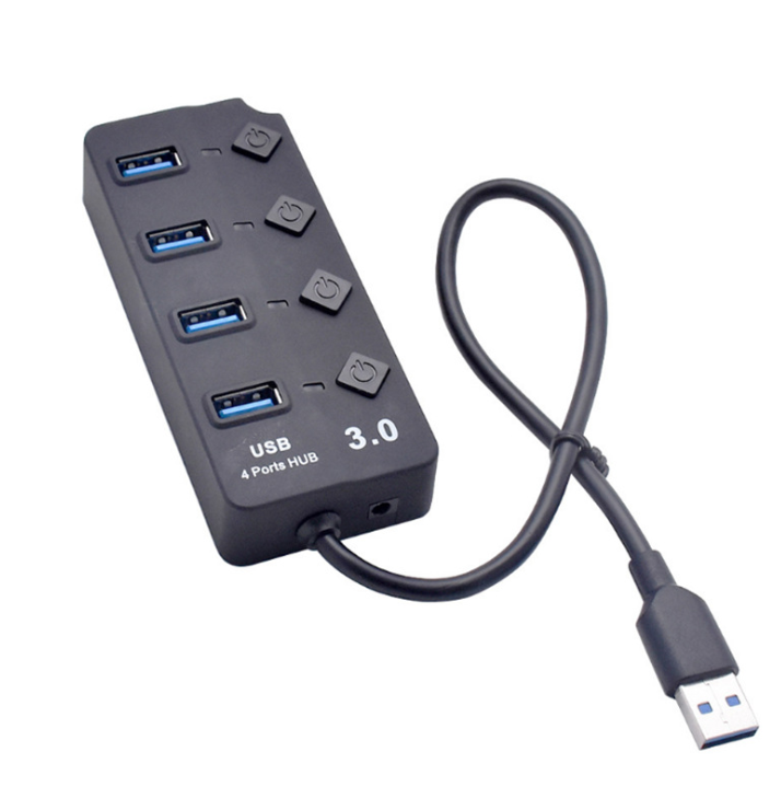 HUB USB 4 PORT 3.0 AVEC INTER
-
17,00 €
HUB USB 4 PORT 3.0 AVEC INTER
-
17,00 €
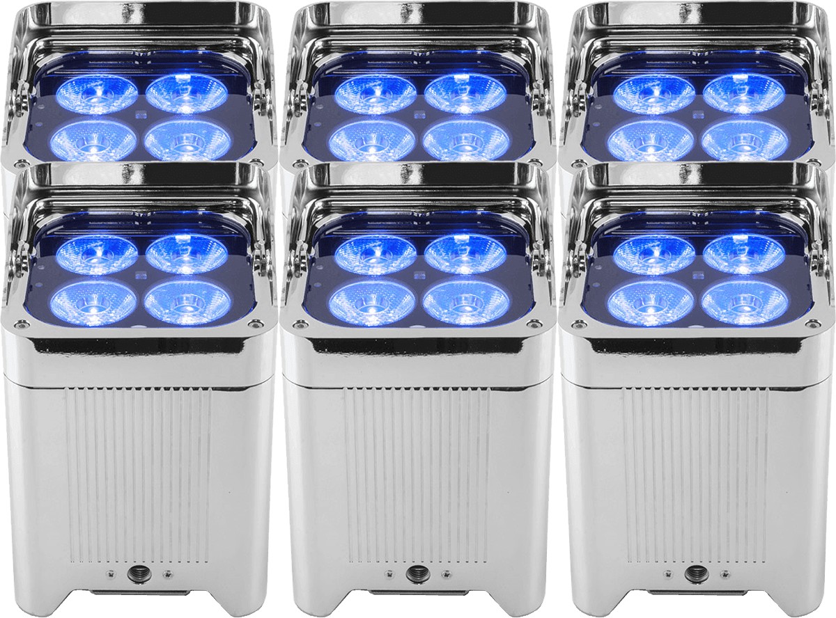 LOCATION PROJECTEUR LED RVB AUTONOME
-
19,00 €
LOCATION PROJECTEUR LED RVB AUTONOME
-
19,00 €
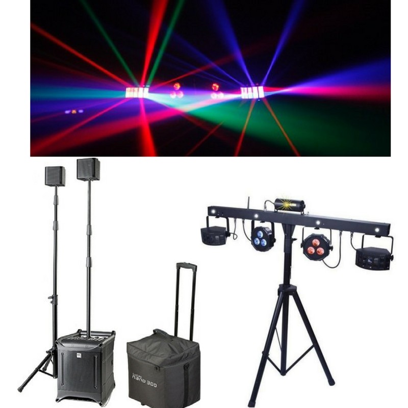 LOCATION PACK SON ET LUMIERES 50 PERSONNES
-
70,00 €
LOCATION PACK SON ET LUMIERES 50 PERSONNES
-
70,00 €
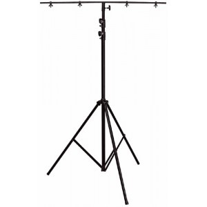
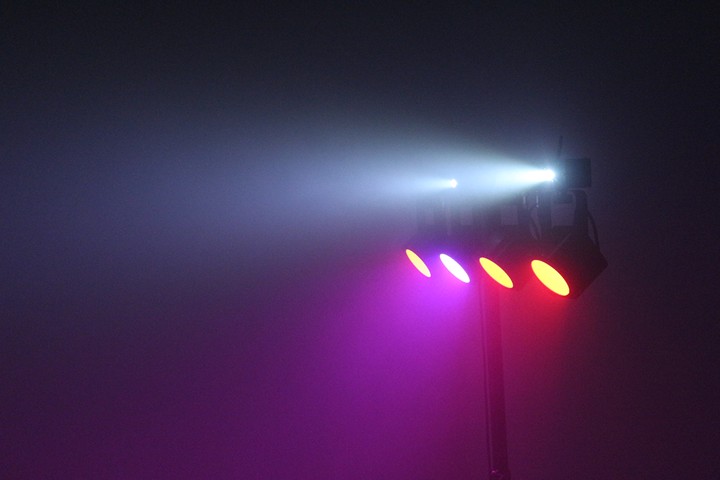 LOCATION BARRE A LEDS + STROBOSCOPE SUR PIED
-
29,00 €
LOCATION BARRE A LEDS + STROBOSCOPE SUR PIED
-
29,00 €
 LOCATION PACK SON ET LUMIERES 150 PERSONNES
-
85,00 €
LOCATION PACK SON ET LUMIERES 150 PERSONNES
-
85,00 €
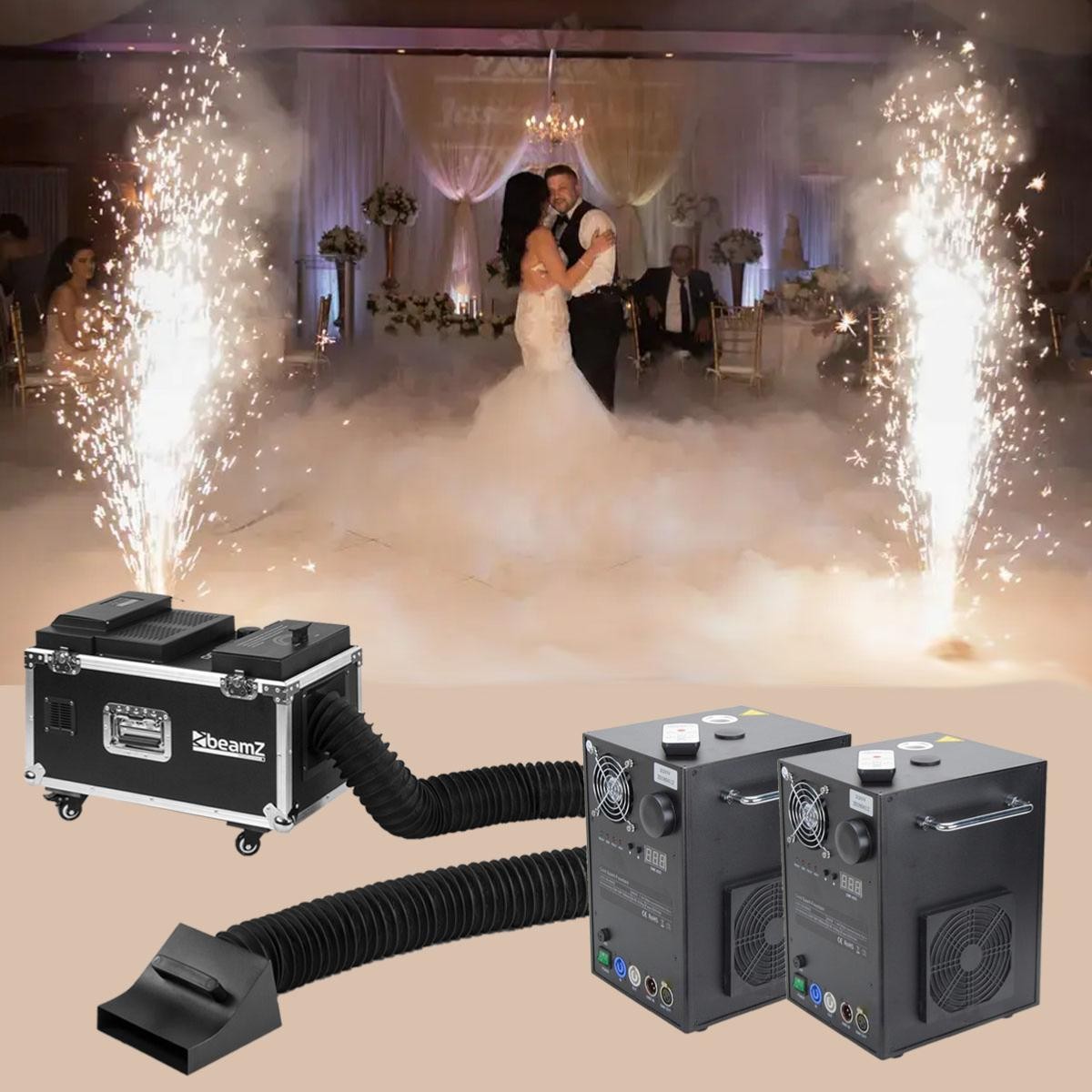 LOCATION PACK MARIAGE ETINCELLES X2 + FUMEE LOURDE
-
159,00 €
LOCATION PACK MARIAGE ETINCELLES X2 + FUMEE LOURDE
-
159,00 €
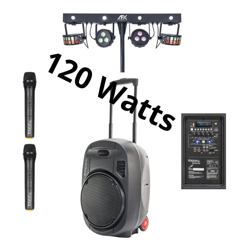 LOCATION ENCEINTE 120WATTS BT USB + LUMIERES
-
59,00 €
LOCATION ENCEINTE 120WATTS BT USB + LUMIERES
-
59,00 €
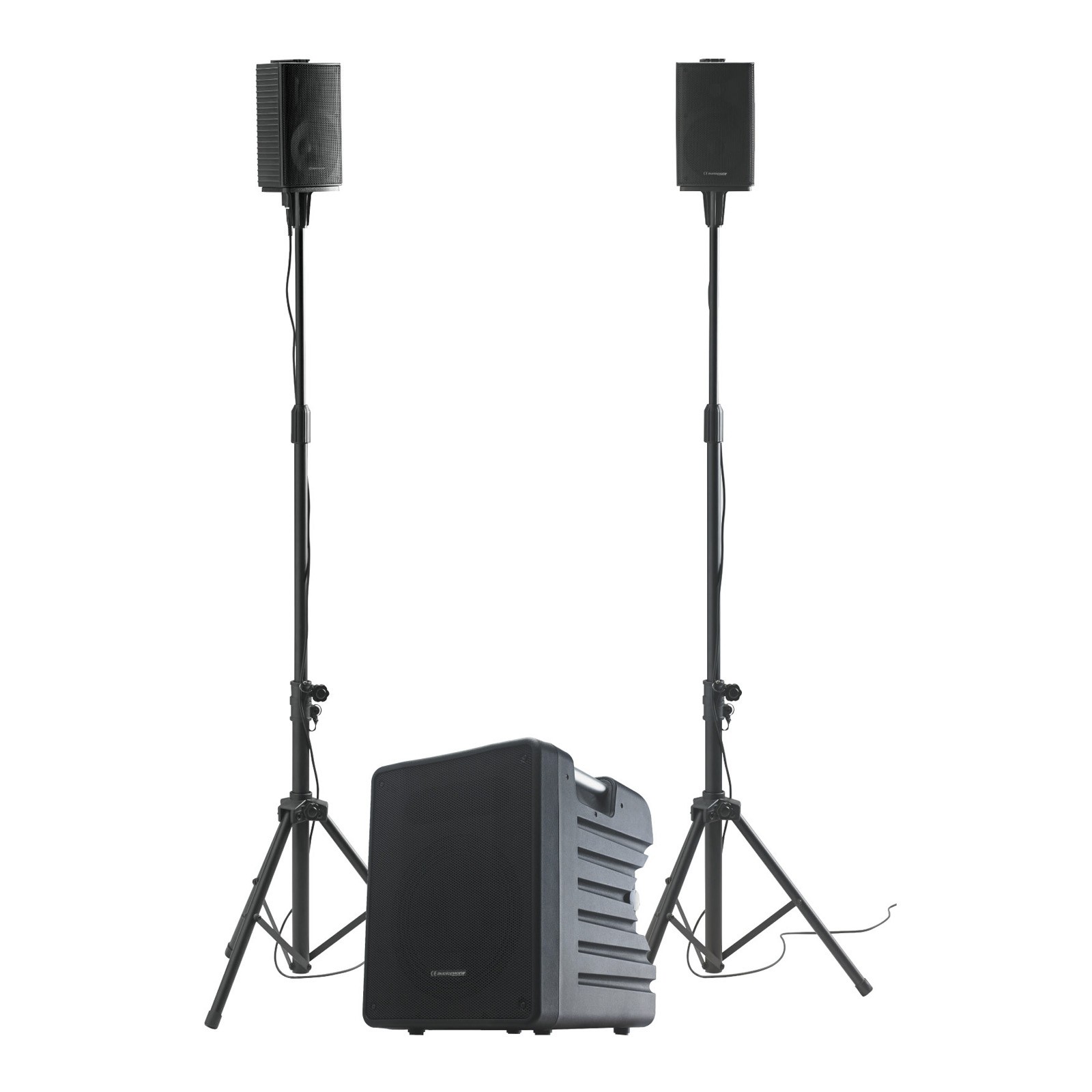
 Location HK Lucas nano 300Watts 50 personnes BLUETOOTH
-
50,00 €
Location HK Lucas nano 300Watts 50 personnes BLUETOOTH
-
50,00 €
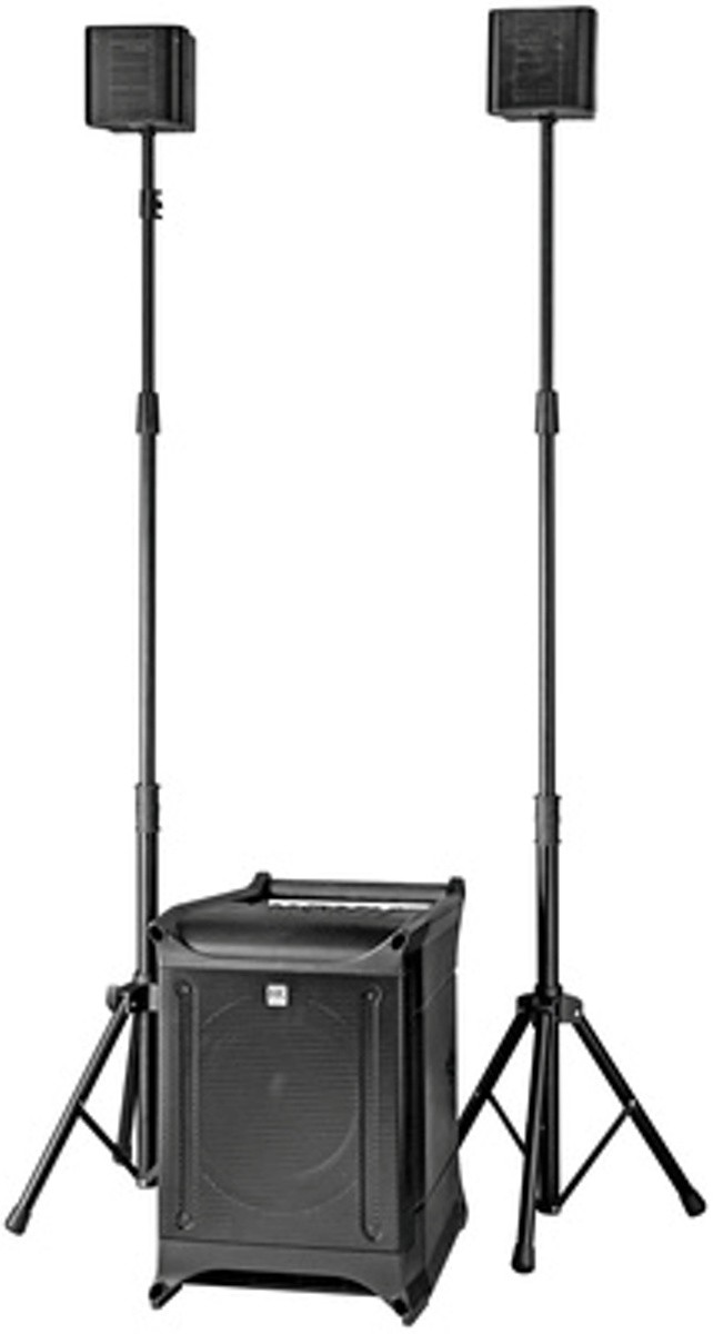 Location HK Lucas nano 600Watts 150 personnes
-
70,00 €
Location HK Lucas nano 600Watts 150 personnes
-
70,00 €
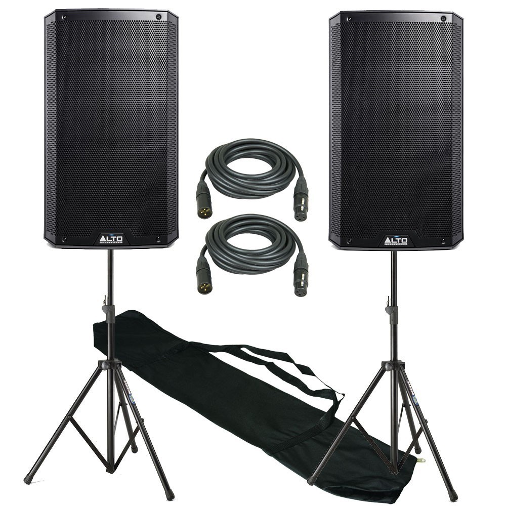 LOCATION ENCEINTE ALTO 550Watts X 2 + BLUETOOTH
-
70,00 €
LOCATION ENCEINTE ALTO 550Watts X 2 + BLUETOOTH
-
70,00 €
 LOCATION ENCEINTE 120Watts, USB + 2 micros sans fil
-
39,00 €
LOCATION ENCEINTE 120Watts, USB + 2 micros sans fil
-
39,00 €
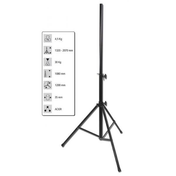 LOCATION PIED ENCEINTE
-
5,00 €
LOCATION PIED ENCEINTE
-
5,00 €
 LOCATION ENCEINTE 180Watts, USB +2 micro sans fil
-
49,00 €
LOCATION ENCEINTE 180Watts, USB +2 micro sans fil
-
49,00 €
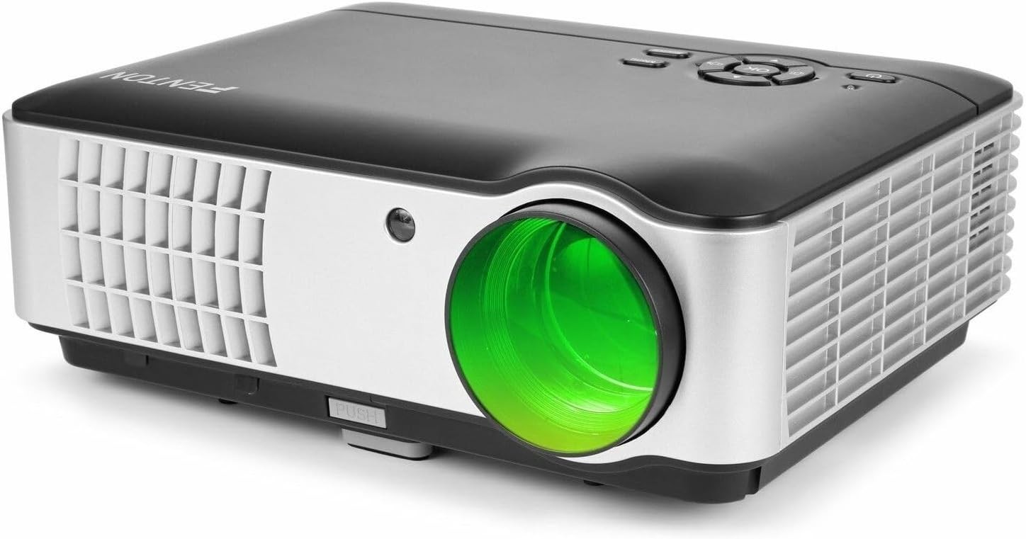 LOCATION Vidéoprojecteur 3000 lumens professionnel
-
20,00 €
LOCATION Vidéoprojecteur 3000 lumens professionnel
-
20,00 €
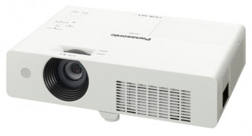 LOCATION Vidéoprojecteur 3800 lumens professionnel
-
35,00 €
LOCATION Vidéoprojecteur 3800 lumens professionnel
-
35,00 €
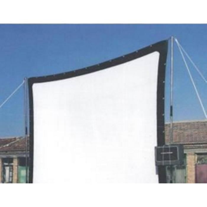 LOCATION ECRAN DE VIDEO-PROJECTION 3.80mts SOUPLE 16/9ème
-
39,00 €
LOCATION ECRAN DE VIDEO-PROJECTION 3.80mts SOUPLE 16/9ème
-
39,00 €
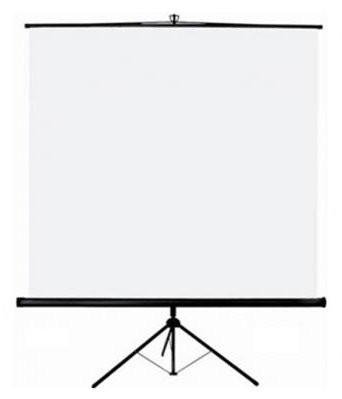 LOCATION ECRAN DE VIDEO-PROJECTION 150x150 SUR PIED
-
15,00 €
LOCATION ECRAN DE VIDEO-PROJECTION 150x150 SUR PIED
-
15,00 €
 LOCATION ECRAN DE VIDEO-PROJECTION 200X200 SUR PIED
-
15,00 €
LOCATION ECRAN DE VIDEO-PROJECTION 200X200 SUR PIED
-
15,00 €
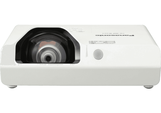 LOCATION VIDÉOPROJECTEUR COURTE FOCALE 3300 LUMENS PROFESSIONNEL
-
55,00 €
LOCATION Vidéoprojecteur 3000 lumens professionnel
-
20,00 €
LOCATION Vidéoprojecteur 3800 lumens professionnel
-
35,00 €
LOCATION ECRAN DE VIDEO-PROJECTION 3.80mts SOUPLE 16/9ème
-
39,00 €
LOCATION ECRAN DE VIDEO-PROJECTION 150x150 SUR PIED
-
15,00 €
LOCATION ECRAN DE VIDEO-PROJECTION 200X200 SUR PIED
-
15,00 €
LOCATION VIDÉOPROJECTEUR COURTE FOCALE 3300 LUMENS PROFESSIONNEL
-
55,00 €
LOCATION VIDÉOPROJECTEUR COURTE FOCALE 3300 LUMENS PROFESSIONNEL
-
55,00 €
LOCATION Vidéoprojecteur 3000 lumens professionnel
-
20,00 €
LOCATION Vidéoprojecteur 3800 lumens professionnel
-
35,00 €
LOCATION ECRAN DE VIDEO-PROJECTION 3.80mts SOUPLE 16/9ème
-
39,00 €
LOCATION ECRAN DE VIDEO-PROJECTION 150x150 SUR PIED
-
15,00 €
LOCATION ECRAN DE VIDEO-PROJECTION 200X200 SUR PIED
-
15,00 €
LOCATION VIDÉOPROJECTEUR COURTE FOCALE 3300 LUMENS PROFESSIONNEL
-
55,00 €


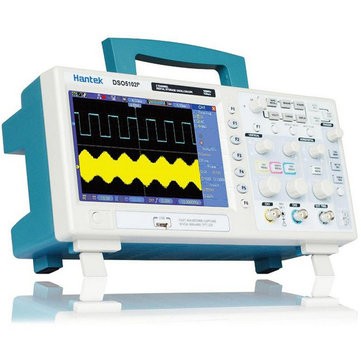
| Model | DSO5202P | DSO5102P | DSO5072P |
| Acquisition | |||
| Sample Rate | Real-Time Sample: 1GS/s Equivalent Sample: 25GS/s |
||
| Acquisition Modes | |||
| Normal | Normal data only | ||
| Pea'k Detect | High-frequency and randon glith capture | ||
| Average | Wavefom Average, selectable 4,8,16,32,64,128 | ||
| Inputs | |||
| Inputs Coupling | AC, DC, GND | ||
| Inpits Impendance | 1MΩ±2% II20pF±3pF | ||
| Probe Attenuation | 1X, 10X | ||
| Supported Probe Attenuation Factor | 1X, 10X, 100X, 1000X | ||
| Maximum Input Voltage | CAT I and CAT II: 300VRMS (10×), Installation Category; CAT III: 150VRMS (1×); Installation Category II: derate at 20dB/decade above 100kHz to 13V Pea'k AC at 3MHz* and above. For non-sinusoidal waveforms, Pea'k value must be less than 450V. Excursion above 300V should be of less than 100ms duration. RMS signal level including all DC components removed through AC coupling must be limited to 300V. If these values are exceeded, damage to the oscilloscope may occur. |
||
| Horizontal | |||
| Sample Rate Range | 500MS/s--1GS/s | ||
| Waveform Interpolation | (sin x)/x | ||
| R'ecord Length | 40'K | ||
| SEC/DIV Range | 4ns/div to 40s/div | 4ns/div to 40s/div | |
| Sample Rate and Delay Time Accuracy |
±50ppm(at over any ≥1ms time interval) | ||
| Position Range | 2ns/div to 10ns/div; (-4div x s/div) to 20ms; |
20ns/div to 80us/div; (-8div x s/div) to 40ms; 200us/div to 40s/div; (-8div x s/div) to 400s |
|
| Delta Time Measurement Accuracy (Full Bandwidth) |
Single-shot, Normal mode:± (1 sample interval +100ppm × reading + 0.6ns); >16 averages:± (1 sample interval + 100ppm × reading + 0.4ns); Sample interval = s/div ÷ 200 |
||
| Vertical | |||
| Vertical Resolution | 8-bit resolution, all channel sampled simultaneously | ||
| Position Range | 2mV/div to 200mV/div, ±2V 200mV/div to 5V/div, ±50V |
||
| Bandwidth | 100MHz | 100MHz | 70MHz |
| Rise Time at BNC( typical) | 3.5ns | 3.5ns | 5ns |
| Analog Bandwidth in Normal and Average modes at BNC or with probe, DC Coupled |
2mV/div to 20mV/div, ±400mV; 50mV/div to 200mV/div, ±2V 500mV/div to 2V/div, ±40V; 5V/div, ±50V |
||
| Math | +, -, *, /, FFT | ||
| FFT | Windows: Hanning, Flatop, Rectamgular, Bartlett, Blackman; 1024 sample point |
||
| Bandwidth Limit | 20MHz | ||
| Low Frequency Response (-3db) | ≤10Hz at BNC | ||
| DC Gain Accuracy | ±3% for Normal or Average acquisition mode, 5V/div to 10mV/div; ±4% for Normal or Average acquisition mode, 5mV/div to 2mV/div |
||
| DC Measurement Accuracy, Average Acquisition Mode |
When vertical displacement is zero, and N ≥16:± (3% × reading + 0.1div + 1mV) only 10mV/div or greater is selected; When vertical displacement is not zero, and N≥16: ± [3% × (reading + vertical position) + 1% of vertical position + 0.2div]; Add 2mV for settings from 2mV/div to 200mV/div; add 50mV for settings from 200mV/div to 5V/div |
||
| Volts Measurement Repeatability, Average Acquisition Mode |
Delta volts between any two averages of ≥16 waveforms acquired under same setup and ambient conditions | ||
| Trigger System | |||
| Trigger Types | Edge, Video, Pulse, Slope, Over time, Alternative | ||
| Trigger Source | CH1, CH2, EXT, EXT/5, AC Line | ||
| Trigger Modes | Auto, Normal, Single | ||
| Coupling Type | DC, AC, Noise Reject, HF Reject, LF Reject | ||
| Trigger Sensitivity (Edge Trigger Type) |
DC(CH1,CH2): 1div from DC to 10MHz; 1.5div from 10MHz to 100MHz; 2div from 100MHz to Full; DC(EXT): 200mV from DC to 100MHz; 350mV from 100MHz to 200MHz; DC(EXT/5): 1V from DC to 100MHz;1.75V from 100MHz to 200MHz; AC: Attenuates signals below 10Hz; HF Reject: Attenuates signals above 80kHz; LF Reject: Same as the DC-coupled limits for frequencies above 150kHz; attenuates signals below 150kHz |
||
| Trigger Level Range | CH1/CH2: ±8 divisions from center of screen; EXT: ±1.2V; EXT/5:±6V |
||
| Trigger Level Accuracy( typical)Accuracy is for signals having rise and fall times ≥20ns |
CH1/CH2: 0.2div × volts/div within ±4 divisions from center of screen; EXT: ± (6% of setting + 40mV); EXT/5: ± (6% of setting + 200mV); |
||
| Set Level to 50%(typical) | Operates with input signals ≥50Hz | ||
| Video Trigger | |||
| Video Trigger Type | CH1, CH2: Pea'k-to-Pea'k amplitude of 2 divisions; EXT: 400mV; EXT/5: 2V |
||
| Signal Formats and Field Rates, Video Trigger Type | Supports NTSC, PAL and SECAM broadcast systems for any field or any line | ||
| Holdoff Range | 100ns ~ 10s | ||
| Pulse Width Trigger | |||
| Pulse Width Trigger Mode | Trigger when (< , >, = , or ≠); Positive pulse or Negative pulse | ||
| Pulse Width Trigger Point | Equal: The oscilloscope triggers when the trailing edge of the pulse crosses the trigger level. Not Equal: If the pulse is narrower than the specified width, the trigger point is the trailing edge. Otherwise, the oscilloscope triggers when a pulse continues longer than the time specified as the Pulse Width. Less than: The trigger point is the trailing edge. Greater than (also called overtime trigger): The oscilloscope triggers when a pulse continues longer than the time specified as the Pulse Width |
||
| Pulse Width Range | 20ns ~ 10s | ||
| Slope Trigger | |||
| Slope Trigger Mode | Trigger when (< , > , = , or ≠ ); Positive slope or Negative slope | ||
| Slope Trigger Point | Equal: The oscilloscope triggers when the waveform slope is equal to the set slope. Not Equal: The oscilloscope triggers when the waveform slope is not equal to the set slope. Less than: The oscilloscope triggers when the waveform slope is less than the set slope. Greater than: The oscilloscope triggers when the waveform slope is greater than the set slope. |
||
| Time Range | 20ns ~ 10s | ||
| Overtime Trigger | |||
| Over Time Mode | Rising edge or Falling edge | ||
| Time Range | 20ns ~ 10s | ||
| Alternative Trigger | |||
| Trigger on CH1 | Internal Trigger: Edge, Pulse Width, Video, Slope | ||
| Trigger on CH2 | Internal Trigger: Edge, Pulse Width, Video, Slope | ||
| Trigger Frequency Counter | |||
| Readout Resolution | 6 digits | ||
| Accuracy (typical) | ±30ppm (including all frequency reference errors and ±1 count errors) | ||
| Frequency Range | AC coupled, from 4Hz Min to rated bandwidth | ||
| Signal Source | Pulse Width or Edge Trigger modes: all available trigger sources The Frequency Counter measures trigger source at all times, including when the oscilloscope acquisition pauses due to changes in the run status, or acquisition of a single shot event has completed. Pulse Width Trigger mode: The oscilloscope counts pulses of significant magnitude inside the 1s measurement window that qualify as triggerable events, such as narrow pulses in a PWM pulse train if set to < mode and the width is set to a relatively small time. Edge Trigger mode: The oscilloscope counts all edges of sufficient magnitude and correct polarity. Video Trigger mode: The Frequency Counter does not work. |
||
| Measure | |||
| Cursor Measurement | Voltage difference between cursors: ΔV Time difference between cursors: ΔT Reciprocal of ΔT in Hertz (1/ΔT) |
||
| Auto Measuerment | Frequency, Period, Mean, Pk-Pk, Cycli RMS, Min, Maximum, Rise time, Fall Time, +Pulse Width, -Pulse Width, Delay1-2Rise, Delay1-2Fall, +Duty, -Duty, Vbase, Vtop, Vmid, Vamp, Overshoot, Preshoot, Preiod Mean, Preiod RMS, FOVShoot, RPREShoot, BWIDTH, FRF, FFR, LRR, LRF, LFR, LFF | ||
| Display | |||
| Display Type | 7 inch 64K color TFT (diagonal liquid crystal) | ||
| Display Resolution | 800 horizontal by 480 vertical pixels | ||
| Display Contrast | Adjustable (16 gears) with the progress bar | ||
| Probe Compensator Output | |||
| Output Voltage( typical) | About 5Vpp into ≥1MΩ load | ||
| Frequency(typical) | 1kHz | ||
| Power Supply | |||
| Supply Voltage | 100-120VACRMS(±10%), 45Hz to 440Hz, CATII 120-240VACRMS(±10%), 45Hz to 66Hz, CATII |
||
| Power Consumption | <30W | ||
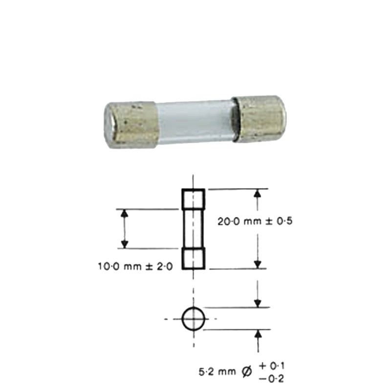
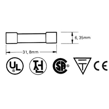
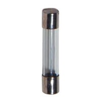
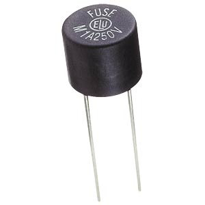
| Fuse | 2A, T rating, 250V | ||
| Environmental | |||
| Temperature | Operating: 32F to 122F (0C to 50C); Nonoperating: -40F to 159.8F (-40C to +71C) |
||
| Cooling Method | Convection | ||
| Humidity | +104F or below (+40C or below): ≤90% relative humidity; 106F to 122F (+41C to 50C): ≤60% relative humidity |
||
| Altitude | Operating: Below 3,000m (10,000 feet); Nonoperaring: Below 15,000m(50,000 feet) |
||
| Mechanical | |||
| Size | Length 385mm, Width 200mm, Height 245mm | ||
| Weight | 3.5KG(with Packing); 2.08KG(without Packing) | ||